• We just finished a fairly major forum upgrade. If you are having problems using the forums, please clear your browser cache and that should clear up any issues. Otherwise post in the Help Thread or email us at forum_moderator@aawforum.org. Happy Holidays!
  • December Turning Challenge: Tree! (click here for details)
  • Congratulations to Vincent Luciani for "Flower Pot" being selected as Turning of the Week for December 23, 2024 (click here for details)
  • Welcome new registering member. Your username must be your real First and Last name (for example: John Doe). "Screen names" and "handles" are not allowed and your registration will be deleted if you don't use your real name. Also, do not use all caps nor all lower case.

Indexing Plate

Router fluting jigs need a large base so they don't tip in usage. The one linked to in post #46 has too small a base. It has holes in the base that I assume are to screw it to large base.

In Paul Howard’s original instructions for his jig (he no longer sells them himself) there was mention of fitting it to a larger base if required.
My home made jig is pretty much the same size as the PH jig and I’ve never experienced any tendency for it to tip as you suggest.
A guy called William Hunt has produced a series of videos of the PH jig in use and I don’t recall him using a larger base?
Before making my jig I did look on the net for inspiration from other users and once again I don’t remember seeing any jigs with what I might term a large base. I’d be interested in seeing one though if you have a kink Doug as I may be missing something?

I should add that Paul Howard mentions using a PVC plate on the bottom of his jig. It is though the same size as the alloy base.
I decided to mount my base on PTFE buttons to make it easy to slide and this works extremely well. I also use other jig components not used on the PH jig such as guide rails and pivot points. I didn’t consider it at the time I drew up my plans but a large base would certainly preclude or at the least make it difficult for me to use some of these other components.

I also made a “pivot base” but have not used it yet apart from a quick test. The mounting is hanging upside down in the picture in case anyone wondered. The part is obviously used in place of the normal long base.
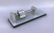

IMG_8344.jpeg
 
My home made jig is pretty much the same size as the PH jig and I’ve never experienced any tendency for it to tip as you suggest.
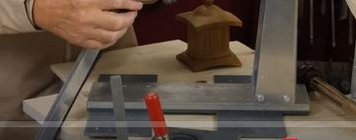
This snip from the video in the first few seconds clearly shows the wider base he is using. I think he may have even mentioned the wider base in the video.

anti tip base.JPG

I've made jigs of this type for use on wood shapers. For the shaper application you're dealing with much greater cutting forces so you need a wide base and heavy mass in the jig. The shaper jigs have been 20 pounds and more. With a smooth, weighted, wide base sliding on a smooth surface the weight is irrelevant.

There's also an issue with using the round nose or 90 degree vee bit that should be avoided if possible. Those bits have a dead zone at the very tip where the peripheral cutting speed is zero. Don Wattenhofer shows a way to overcome the dead zone by inclining his router 45 degrees to the workpiece. That could also be done with round nose bits.
 
Last edited:
Don Wattenhofer shows a way to overcome the dead zone by inclining his router 45 degrees to the workpiece.
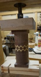
That was an idea I borrowed from John Lucas the other reason for it is the V bits do not cut an accurate 90 degree V and my project was cutting a zig zag joint ( also borrowed from John Lucas). The glue up here illustrates the need for accuracy in not only the 90 degree cut but the indexing as well. DSC00799.JPG
 
This snip from the video in the first few seconds clearly shows the wider base he is using. I think he may have even mentioned the wider base in the video.

View attachment 62665

I've made jigs of this type for use on wood shapers. For the shaper application you're dealing with much greater cutting forces so you need a wide base and heavy mass in the jig. The shaper

There's also an issue with using the round nose or 90 degree vee bit that should be avoided if possible. Those bits have a dead zone at the very tip where the peripheral cutting speed is zero. Don Wattenhofer shows a way to overcome the dead zone by inclining his router 45 degrees to the workpiece. That could also be done with round nose bits.

That’s the first time I’ve seen a wide base like that used. I’ve cut many pieces with my jig and it’s only 100mm wide.

Provided the cutter doesn’t overhang the base which is also free to slide I don’t see the problem you’re experiencing.

As for the cutters you mentioned, I’ve not had a problem with them. If you look at the pictures I posted earlier these, and several others were cut with V bits. Members at my club have also used bull nosed cutters.

This is the base of a candlestick I did some time ago, again with a V cutter. The cut is slightly curved.

IMG_9960.jpeg
 
As for the cutters you mentioned, I’ve not had a problem with them. If you look at the pictures I posted earlier these, and several others were cut with V bits. Members at my club have also used bull nosed cutters.
Your work looks good done with vee bits. It's not a point worth debating though. "if possible" cutters with the dead zone should be avoided and they usually are both in woodworking and metalworking.
 
Router bits with a “dead zone” as you put it are so commonly available it makes me wonder who might be buying them if they cause such a problem? And of course many router bits have this “dead zone” not just V or bull nose varieties. I’ve cut slots in wood with a straight router bit many times.

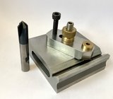
Attached is a picture of a Finger Plate I made made years ago. The 90° V in the top was made with a V bit and then the relief was cut at the same setting with a small slot drill. Next to the Finger Plate is a carbide Drill Mill I’ve used for cutting V’s in both steel and aluminium alloy.

Edit: Slot drills used for cutting metals also have this “dead zone” but are still commonly used in industry to make plunge cuts for blind slots.

IMG_9961.jpeg
 
There's also an issue with using the round nose or 90 degree vee bit that should be avoided if possible. Those bits have a dead zone at the very tip where the peripheral cutting speed is zero. Don Wattenhofer shows a way to overcome the dead zone by inclining his router 45 degrees to the workpiece. That could also be done with round nose bits.

Not sure what you mean about a dead zone, I've had no issues with V bits. (but not a huge amount of experience) Are you talking about the very center point? It doesn't seem to be an issue because there's really no wood being removed there. (especially with a round nose)
 
Router bits with a “dead zone” as you put it are so commonly available it makes me wonder who might be buying them if they cause such a problem? And of course many router bits have this “dead zone” not just V or bull nose varieties. I’ve cut slots in wood with a straight router bit many times.

Maybe the "dead zone" hype is generated by other tool manufacturers trying to make their products/methods sound better. I guess it could also be poor quality bits causing issues for some.
 
There are certainly lots of poor quality TCT “budget” router bits out there. I try to get solid carbide ones, at least in the smaller sizes, from a respected UK supplier. Sometimes though it’s hard to justify the price for what might be a one off job.
 
Maybe the "dead zone" hype is generated by other tool manufacturers trying to make their products/methods sound better. I guess it could also be poor quality bits causing issues for some.

No, it's not hype at all. It a very well known problem. It's a fact, the center of the cutters have zero cutting speed. Companies making intricate wood parts like musical instrument makers spend (literally) hundreds of thousand$ on multi-axis machinery and related software to avoid dead zone cutting.

There are certain situations where it can't be easily avoided especially for hobbyists with limited budgets. It doesn't matter whose bits you buy. Don Wattenhofer showed an easy and clever way to avoid the problem (John Lucas apparently should get credit for the method).
 
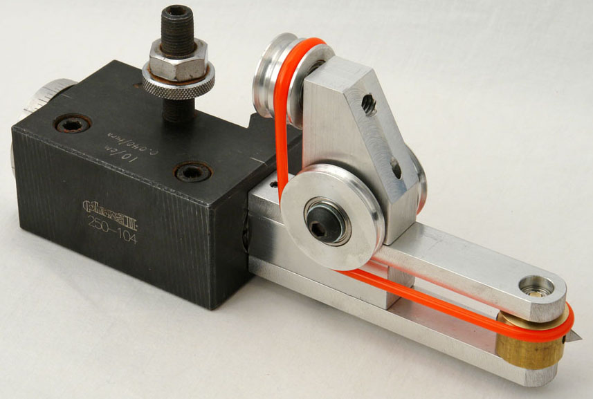
This discussion about bit rotational speed is one reason why having options on a Rose engine is so great! We can use cutters like this and swap out the cutters on the end for the desired shape.

CuttingFrame.jpeg
 
This discussion about bit rotational speed is one reason why having options on a Rose engine is so great! We can use cutters like this and swap out the cutters on the end for the desired shape.

CuttingFrame.jpeg
Yes indeed. I’ve actually made some of my own HSS flycutters for decorating the outside of some small boxes I intend to make.
Sadly the lowest speed on my router is 11,500 rpm which seemed rather too fast. I was quite surprised with the results of my first test though. I would still like to try a much lower speed and have spied a milling motor with a bottom speed of 4000 rpm. I have begged the question of what speed Ornamental lathe or Rose engine operators use but haven’t received an answer on the topic.

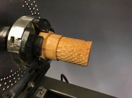
This is my first test on some Yew. It was cut at 11,500 rpm. Curiously I did a second test on the same piece of wood and the result wasn’t quite as good until I turned the speed up a bit! I understand that some folks reinforce the wood with various solutions to harden it before making the cuts. Lots to learn on this new to me topic.

IMG_8365.jpeg
 
You can buy a router speed control really cheap. People are always asking if they would work on lathe motors. They won't. They do work perfectlybon routers.
 
You can buy a router speed control really cheap. People are always asking if they would work on lathe motors. They won't. They do work perfectlybon routers.
I’ve begged this question of several people more knowledgeable about the subject than myself and have been told a speed control won’t work on a router with its own built in speed control circuit. It seems these controllers are designed for single speed routers? A member of my club has however suggested I speak with an another member that has designed his own electronic devices to see if he can help. A speed controller will be a much cheaper option for me if it can be made to work. Hopefully I’ll be speaking with him tomorrow.

Edit: I found this online a while back.

 
Last edited:
Have heard that the speed controller could burn up the motor. No experience just forum talk. Found something on router forums.com that it will not work if router has a capacitor. Just ask the question in google and get lots of answers and reviews of controllers.
 
I did wonder if bypassing the router’s internal speed control and using an external unit may work. I’ll be having a chat with someone tomorrow to see if they have any insights.
 
I finished the bowl mounted with base towards tailstock. I turned a shallow recess inside the bowl to grab it with 50mm extended jaws and used the live center as additional support. It was a lot easier to set up the jig and move the router in this arrangement. Now next question, how do you people do the flutes without burning the wood with router bit? I slowed the router down and that helped, also keeping it moving and not stopping helps. Any other suggestions? I tried sanding the stain out with 320 but that was not working, might try 220 next or dye them black if that doesn't work. As far as router speed controller as in posts above I made my own from a duplex recepticle and a rotary dial light dimmer, but I only use it on my Dremel and the small Rockwell router you see in the picture.
 

Attachments

  • IMG_2367 Jig.jpg
    IMG_2367 Jig.jpg
    488.2 KB · Views: 21
  • IMG_2368 Fluted Bowl Bottom.jpg
    IMG_2368 Fluted Bowl Bottom.jpg
    575.3 KB · Views: 19
I did wonder if bypassing the router’s internal speed control and using an external unit may work. I’ll be having a chat with someone tomorrow to see if they have any insights.
Don't understand why you need an external speed control if the router has a speed control built in???
 
Don't understand why you need an external speed control if the router has a speed control built in???
The minimum speed on my router is 11,500 rpm which is too fast for some jobs. I’ve seen some that go as low as 4,000 rpm but they are quite expensive. An external speed control might allow me to lower the speed to something more useful.
 
A fourth option is a "spin index fixture", which has 360 positions so any number of combinations that will divide into 360 and result in a whole number is possible. Example 12 stops would be every 30 degrees as in 0, 30, 60, 90, etcetera however 360 / 16 = 22.5 so 16 would not be settable.
View attachment 62062
If you do a search for "Spin Index Fixture" you would get an idea what is available. The method I used to link to my headstock was to mount the fixture on the top of the lathe and connect to the spindle with a chain loop. If you are just going to be fluting many of the lathes based on Chinese castings have limited indexing built in.
A couple of pictures, should be self explanatory but ask away if you need any more. I made the motor mount out of 5/8” thick alloy bar.

View attachment 62298
View attachment 62300
Awesome. How much is off the sheilf and how made from scratch?
 
Awesome. How much is off the sheilf and how made from scratch?
Hi Harold, just made from off the shelf Alloy Channel and plate. I bought a motor mount for the first version but I wasn’t very happy with the router. The second router had a different diameter collar so I made a mount for it from 5/8” thick alloy plate.

Much of this could just as easily be made from good quality ply or hardwood though. I chose to made PTFE feet for mine so it moves about easily.
 
I'm interested in buying an indexing plate. I've researched past threads on this and have a couple questions. From what I've found Alisam and Chefware are the only two brands I can find. For 1 1/4" spindle Alisam offers a 10" aluminum wheel that has 144, 120, 98, and 16 holes. Chefware offers a 12" steel plate for 1 1/4" spindle with 192, 144, 120, 90, 88, and 56 holes. How important is it to have the extra holes offered on the Chefware plate? My lathe is 15" swing and I'm afraid the 12" wheel will get in the way of the router. My main interest is using a router to do fluting on bowls and possibly spindles. I have made a plate to mount in the banjo and the brackets to allow the trim router to move about the base. I also ordered a 3" spindle extender to move the chuck away from the headstock to allow more room for the router to move about. Thanks in advance.
Vincent, I do make a complete set of index wheels and the rest, look at my site, "segmentedturning.org"
 
I'm interested in buying an indexing plate. I've researched past threads on this and have a couple questions. From what I've found Alisam and Chefware are the only two brands I can find. For 1 1/4" spindle Alisam offers a 10" aluminum wheel that has 144, 120, 98, and 16 holes. Chefware offers a 12" steel plate for 1 1/4" spindle with 192, 144, 120, 90, 88, and 56 holes. How important is it to have the extra holes offered on the Chefware plate? My lathe is 15" swing and I'm afraid the 12" wheel will get in the way of the router. My main interest is using a router to do fluting on bowls and possibly spindles. I have made a plate to mount in the banjo and the brackets to allow the trim router to move about the base. I also ordered a 3" spindle extender to move the chuck away from the headstock to allow more room for the router to move about. Thanks in advance.
I became interested in open segment turning this past winter. So I needed an index plate. But I wasn't sure how much or how often I'd need/use it. I'm cheap and didn't want to spend money that wouldn't be used often.
So I built two using 1/4" MDF. Downloaded templates from blocklayer.com, glued them to the mdf and cut it out on my bandsaw and drilled 1/8" holes.
Built an indexing jig that fit my lathe beds with scraps I had on hand.
None of that was difficult just picky to be accurate.
I made two. One with 48 holes for a 24 segment vessel and one with 96 for a 48 segment.
They worked fine for the 3 projects I've done so far and if I want different spacing it's easy to build another.
The 1 1/4" hole to fit my drive spindle was easy since the template has a spot on centre mark.
 
I considered making my own but someone pointed out the the chuck still has good contact with the spindle register when using a thin steel or alloy indexing disc. The disc I bought from Paul Howard is only 2mm thick. I’m not sure how well a chuck will fit on some lathes if you use a much thicker disc? I know when I spin my Axminster chuck on my lathe spindle with the indexing disc fitted it’s rock solid.
I recently bought some 2mm thick alloy plate to make another disc but I’ve not got round to it yet. Another job to add to the list!
 
The dead spot on V groove bits is real. They leave an unsightly button in the groove. I put sandpaper around a square corner on woid and sand the grooves. Using a straight bit mounted at45 degrees eliminates this.
I have 4 different index wheels. 2 are pretty thick but i have not measured them. They work fine on my powermatic but i havent used them on another lathe.
 
Vincent, I do make a complete set of index wheels and the rest, look at my site, "segmentedturning.org"
Thanks for the information Tom. I have already purchased an index plate, I wasn't aware of your product. I looked your website over and found it interesting, especially the tab for the math of segments.
 
Back
Top