• We just finished moving the forums to a new hosting server. It looks like everything is functioning correctly but if you find a problem please report it in the Forum Technical Support Forum (click here) or email us at forum_moderator AT aawforum.org. Thanks!
  • Beware of Counterfeit Woodturning Tools (click here for details)
  • Johnathan Silwones is starting a new AAW chapter, Southern Alleghenies Woodturners, in Johnstown, PA. (click here for details)
  • Congratulations to Peter Jacobson for "Red Winged Burl Bowl" being selected as Turning of the Week for April 29, 2024 (click here for details)
  • Welcome new registering member. Your username must be your real First and Last name (for example: John Doe). "Screen names" and "handles" are not allowed and your registration will be deleted if you don't use your real name. Also, do not use all caps nor all lower case.

dust collection images

Joined
Oct 22, 2009
Messages
79
Likes
1
Location
Milford, PA
I am looking to improve the collection of dust around the lathe. I have a good quality Oneida system, but I just have a single drop above the lathe. It pulls in the fine particles that float up, but it seems most drop DOWN. My initial thinking is to construct a hood that can slide behind the lathe and be movable.

I would like to see images of what people have done that maximizes the collection. Also, experiences with hoods and best place to position it.

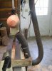
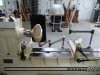
See the attached image. The 5" drop is just visible in the top of the image.
 

Attachments

  • IMG_5777.jpg
    IMG_5777.jpg
    550.6 KB · Views: 308
Joined
Jul 14, 2010
Messages
207
Likes
143
Location
College Station, TX
Dust Collection Setup

My lathe has a built-in mounting bracket. I mounted my dust hood (attached to a cyclone dust collector) on an articulated stand similar to Gary Sanders' light stand and bolted it to the bracket. As shown in attached photos the setup is very versatile. You can move the hood anywhere along the lathe right where you are sanding. My architect's lamp is mounted on a similar stand and the lamp and hood can move independently without getting into each other's way.
 

Attachments

  • Dust hood-1.jpg
    Dust hood-1.jpg
    115.7 KB · Views: 255
  • Dust hood-2.jpg
    Dust hood-2.jpg
    114.3 KB · Views: 232
  • Dust hood-3.jpg
    Dust hood-3.jpg
    96.4 KB · Views: 235
Joined
Jan 18, 2006
Messages
87
Likes
2
Location
VA
Here's mine. Big Gulp in the rear, attached to the headstock via a piece of T-track, so it slides along with the headstock, and pivots and slides front to back. HVAC floor boot in the front. Plug for that is shown on the ways. That is just stuck on the front of the ways with 4 big RE magnets.
 

Attachments

  • image_13.jpg
    image_13.jpg
    97.9 KB · Views: 213

john lucas

AAW Forum Expert
Joined
Apr 26, 2004
Messages
8,337
Likes
3,595
Location
Cookeville, TN
I gave up on collecting the bigger chips. Because of all my varied turning styles chip collection was useless. You would need 10 times the volume of suction that I have to collect those. In fact I was cleaning the shop the other day and found shavings on a shelf that is 1 foot from the ceiling, 10 feet away from the lathe.
I have a 4" hose connected to a 5x12 air conditioning vent sitting right behind whatever is turned. I can move it to pick up as much as possible.
For the rest I just use a garden rake and a broom to sweep them up later. I don't have to empty the dust collector as often since it's all on the floor. :)
 

Dennis J Gooding

Beta Tester
Beta Tester
Joined
Apr 10, 2010
Messages
827
Likes
747
Location
Grants Pass, Oregon
My approach is simple and works well for me. I have an 8-foot section of 4-in flexible hose attached to the overhead DC system that loops down almost to the floor and back up to near the lathe spindle. The free end has a band clamp with a large rare-earth magnet epoxied to it. Therefore the business end of the hose can be positioned in a wide variety of locations as needed. I can't prove it, but I believe that the airflow pattern for suction into an orifice is roughly the reverse of that for air being blown from the orifice. If so, then when designing the collector geometry one should think in terms of what would produce the most airflow past the object being sanded if the system were blowing air instead of sucking it. As shown in the picture, the air inlet in my system is pointed at and close to the turning. BTW, the curvature of the flexible hose is produced by stitching together several loops of the reinforcing wire with a piece of steel wire.

Dennis
 

Attachments

  • IMG_3477p.jpg
    IMG_3477p.jpg
    342 KB · Views: 193
Joined
Mar 17, 2010
Messages
85
Likes
2
Location
Port Alberni BC
My approach is simple and works well for me. I have an 8-foot section of 4-in flexible hose attached to the overhead DC system that loops down almost to the floor and back up to near the lathe spindle. The free end has a band clamp with a large rare-earth magnet epoxied to it. Therefore the business end of the hose can be positioned in a wide variety of locations as needed. I can't prove it, but I believe that the airflow pattern for suction into an orifice is roughly the reverse of that for air being blown from the orifice. If so, then when designing the collector geometry one should think in terms of what would produce the most airflow past the object being sanded if the system were blowing air instead of sucking it. As shown in the picture, the air inlet in my system is pointed at and close to the turning. BTW, the curvature of the flexible hose is produced by stitching together several loops of the reinforcing wire with a piece of steel wire.

Dennis
I think you should experiment with a pick-up at least 6" square. You might be surprised at the improvement in picking up fines. A higher volume lower velocity is always better! The existing setup tunnels. Ron
 

john lucas

AAW Forum Expert
Joined
Apr 26, 2004
Messages
8,337
Likes
3,595
Location
Cookeville, TN
For a short while Powermatic had a dust collector hood for sale that looked like something NASA would design. It had a central aerodynamic sort of wing that I assume helped speed up the flow of air and help funnel it down. I could not find it on their website. I thought about buying one a while back but didn't go to the trouble of calling them to see if it exists.
 
Joined
May 16, 2005
Messages
3,540
Likes
15
http://hyperphysics.phy-astr.gsu.edu/hbase/forces/isq.html

Closer you get, better things work. If you power sand, it's easy to adjust the pickup and the producer positions to get maximum benefit from both gravity and proximity. Restriction of the inlet size will give some increase in velocity, though the impeller is really only capable of a certain volume at any given pressure, so it's not a worthwhile course of action overall.

Production of long shavings can lead to rats nest clogs in any bend or restricted area of the DC hose. I use a bag to collect the big stuff. Bit of a modification in cutting technique will collect almost every shaving from the outside of a bowl as produced, while a tabletop and back wall takes care of what's produced from the inside without having to bend, reach and shovel.
 

john lucas

AAW Forum Expert
Joined
Apr 26, 2004
Messages
8,337
Likes
3,595
Location
Cookeville, TN
MM I was thinking the Powermatic dust chute was trying to take advantage of the Bernoulli theory and of course probably the inverse square (I'm a photographer and had to use that law many many times in lighting)
 

Attachments

  • Bernoulli's theory.jpg
    Bernoulli's theory.jpg
    2.2 KB · Views: 90
Joined
May 16, 2005
Messages
3,540
Likes
15
Difficulty applying the principle here is what I mentioned in the post. The impeller in the DC itself. It will only move so much air at X inches resistance. Can't vary the motor rpm, which might help - or not, if their design team has optimized angle and scoop - get more volume going, so best you can do with a Bernoulli concept would be to give some direction to the flow. To use your photo lighting analogy, barn doors will not add to the light, just control the spill.
 

Dennis J Gooding

Beta Tester
Beta Tester
Joined
Apr 10, 2010
Messages
827
Likes
747
Location
Grants Pass, Oregon
I think you should experiment with a pick-up at least 6" square. You might be surprised at the improvement in picking up fines. A higher volume lower velocity is always better! The existing setup tunnels. Ron

I would agree on the higher volume part, particularly if you are trying to flush out a large area. However, sanding dust comes off the work piece at a rather high velocity and a higher velocity of air at the work piece moving toward the collector is needed to capture it before it spreads out and is breathed in by the turner. When I sand, I am able to see a column of dust moving directly from the sander to the mouth of the hose.
 
Joined
Oct 22, 2009
Messages
79
Likes
1
Location
Milford, PA
good information

I want to thank everyone who made a suggestion or posted a video or information.

What I did was construct a plywood box that I attach behind the piece on my aux bed. I can move it in and out as well as rotate. The 5" line will connect to the rear of it.

I am also rigging up a small computer fan to create a small amount of laminar flow of air towards the intake. I understand from a few of the commenters that a small amount of airflow over the piece makes a huge difference.

I should have everything tested in a few weeks (waiting for my flex hose to arrive).

In the longer run, I like what Robo Hippy built. For large sanding jobs that will create a lot of dust, it seems like the ticket. Much like the hood One Way has, but of course, at a fraction of the cost.

thanks.

Ed
 

Attachments

  • IMG_2240.jpg
    IMG_2240.jpg
    527.2 KB · Views: 97
Back
Top