• It's time to cast your vote in the January 2025 Turning Challenge. (click here for details)
  • Conversations are now Direct Messages (click here for details)
  • Congratulations to Alan Weinberg for "Elm Burl Bowl" being selected as Turning of the Week for January 27, 2025 (click here for details)
  • Welcome new registering member. Your username must be your real First and Last name (for example: John Doe). "Screen names" and "handles" are not allowed and your registration will be deleted if you don't use your real name. Also, do not use all caps nor all lower case.

Searching for numbers

Joined
May 8, 2019
Messages
326
Likes
145
Location
Funen, Denmark
I've been searching both the forum and the WWW for details on the old, square version of the Ellsworth Jig. I also tried to locate a sample on my side of the pond for study. No luck.
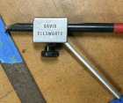
IMG_20190517_144805.jpg

(Photo courtesy of hockenbery)

Would an owner of one be so kind as to provide a few measurements?

I'm NOT into copying or a DIY version - plenty of info on that on the net. I'd simply like to have a closer look at the details of the jig and how they differ from the present version, that I own and use. Honestly paid for, costums and all!

I'm fully aware of the similarities in function and grinding results as described well in other threads, this is all about curiousity and my own process of trying to understand at least some of the "whys" of jig sharpening.

The figures, I'm looking for are these. Since English is (obviously!) not my mother tongue, I've tried to illustrate each wanted measurement with a primitive drawing.

A) Length of the jig head
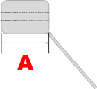
1558168410781_A.png

B) Distance from the bottom of the jig head to the "roof" inside the hole that supports the top of the gouge
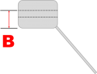
B.png

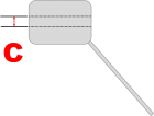
C) Max. height of the hole in the jig head
C.png

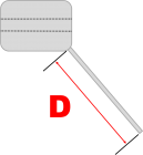
D) The length of the leg

D.png

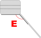
E) The leg angle in relation to the bottom of the jig
E.png


Thanks in advance for any help, you may be able to provide!
Lars

PS: Admin, if in any way inappropriate, please let me know!
 
I have the older rectangular one and will get the measurements as soon as I finish my porridge. I think that I have the dimensions memorized, but sometimes my memory isn't quite what I remember.

Porridge finished. Here are the requested dimensions:
A = 2¼" (57 mm)
B = 1¼" (32 mm)
C = 11/16" (17 mm)
D = 5 9/16" (141 mm)
E = 45°​
The nose of the gouge should extend 2" out of the jig and the pivot point should be set so that the bevel angle on the nose of the gouge is 60°.

Years ago before David Ellsworth was selling his jig he shared information with dimensions so that anybody could make their own jig. It was also available on several websites including the Woodcraft site. You could actually make the block any size that you want as long as the following three dimensions are set as follows:
  • The arm is 45° to the gouge
  • If you draw the centerline of the gouge and the centerline of the arm, then the distance from the intersection of these two centerlines to the pivot end of the arm is exactly 7" (178 mm)
  • The distance from the intersection to the tip of the gouge is exactly 3⅛" (79 mm)
The intersection described above is at the dead center of the aluminum block. Because it is all but impossible to reference dimensions from an imaginary point in the middle of a round bar it is more practical to choose a reference such as the front face of the jig or the tip of the gouge.

Here are a couple other dimensions:
  • Height of the aluminum block = 1⅝" (41 mm)
  • Width of aluminum block = 1⅜". (35 mm)
Hope this helps.
 
Thank you VERY much for the very complete answer.
I'm almost sure that I saw a picture showing the inside profile but I can't find it again with the search function.
Is it correct that the hole in the jig has a round profile but with a flat top?

Lars
 
It's a square hole, but I think that there a number of configurations over the years. The aluminum casting on mine was very sloppy and I had to do a lot of work with a file to clean up the square hole to make it usable. Originally, the locking screw was just an ordinary thumb screw. Later I upgraded the screw with a swivel tip thumb screw.

swivel.jpg
 
Thanks once more.
The present version seems well made but one thing puzzles me.
To achieve a flat "roof" in the round hole for the gouge to register against, they have mounted one steel (?) pin a third from the front.
With no pin behind the centre, tightening the thumb screw in the middle makes the gouge lean about 3° forward in relation to the jig axis.
Surely without much impact on the sharpening, it still makes my eyes itch.
 
You should see the "Vector" jig designed by Johannes Michelsen. While it is intended to create his grind on a bowl gouge, it can also be used to create an Ellsworth grind because the dimensions are precisely the same as the Ellsworth jig. The hole is round, but the "V" block with the red stop block orients the tool correctly and also sets the correct protrusion. It is beautifully machined and anodized and has a price tag to match.

image.jpeg
 
Back
Top