• November Turning Challenge: Puahala Calabash! (click here for details)
  • Sign up for the AAW Forum Pre-Holiday Swap by Monday, November 4th (click here for details)
  • Congratulations to Ted Pelfrey for "Forest Floor" being selected as Turning of the Week for November 4, 2024 (click here for details)
  • Welcome new registering member. Your username must be your real First and Last name (for example: John Doe). "Screen names" and "handles" are not allowed and your registration will be deleted if you don't use your real name. Also, do not use all caps nor all lower case.

Powermatic 3520B VFD Replacement

Joined
Apr 19, 2019
Messages
1
Likes
5
Location
Rockland, Maine
About a week ago I had the VFD on my 3520B go out with a puff of smoke. I found two of the capacitors inside had blown. So I purchased and soldered on replacements but the failure also took out the controller board. In researching a replacement as I was not about to spend $600 on a 20 year old designed VFD I looked to see what I could do to replace it with something newer and more cost effective.

After a bit of research, I landed on a Lapond SVD-P 3hp unit that I found on amazon for a little under $150 with a 5% off coupon. They do offer a different model that is 2hp that is only $100 and would do just fine but I would have been giving up the brake resistor which helps the lathe slow those big bowl blanks down quicker. There is also a 2hp version of the SVD-P but going over size means the VFD doesn't have to work as hard.

Here is what I had to do to make the new VFD work with the Powermatic motor and controls.

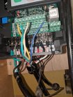
Here we can see what looks like a jumble of wires but it is not actually all that difficult to wire this up. I would recommend doing the larger cables on the bottom first as the smaller ones will get in the way.IMG_20190424_094103.jpg
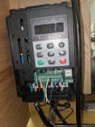
On the bottom left of the VFD we have the power in from the outlet which is 220V single phase. Being single phase the white and black can be switched without harm. Black and White go to L1 and L2. The greenwire goes to the ground on the left most terminal. You'll notice all of these have additional wires.The second Green wire on the ground comes from the motor. The Gray and Red wires are for the RPM readout. They, like the black and white wires does not matter which ones go where. You may have to strip away some of the covering from the main wire bundle to get the Red and Gray wires to connect down, while the rest of the bundle connects above to the other terminal blocks.
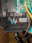
IMG_20190424_094131.jpg
Now looking at the lower right hand side of the VFD we have the brake resistor and motor connections. The brake resistor goes to the terminal towards the middle marked with the + and to the "PB" terminal, again these can be switched without harm. Now the remaining 3 wires from the motor do have an order to them as they are 3 phase 220V. Red goes to U, Black to V, and White to W.
IMG_20190424_094120.jpg
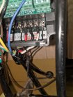
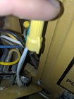
Now to connect the headstock controls we have to make a little modification to get everything to work right. The right most leg of the potentiometer is usually connected to the blue wire from the on/off switch. This will not work with this VFD. To get around the conflict we remove the white lead wire from potentiometer to the blue wire and instead connect it to a new wire that we add. I had a brown wire of about the same gauge so that is what I used. Route your wire through the head stock so that it won't get caught on any of the moving bits. You can wire tie it to the main bundle if you like. Make sure your blue wire is still connected securely to itself as it is still needed.IMG_20190424_094310.jpg
Now onto hooking up the controls to the VFD. For the potentiometer we have the Yellow in the +10V terminal, Green in the AI1 terminal, and the new Brown wire to the GND terminal just below the+10V and AI1. The forward and reverse Black and White wires go to DI1 and DI2. The blue wire goes to the COM terminal.IMG_20190424_094115.jpg Now on to programming the VFD to our needs. This seems a bit intimidating but once you get the hang of the navigation it is pretty easy and explained pretty well in the manual which I do recommend on still skimming.
First we want to input our motor information. For this we are going to select P1 and start setting P1-00 through P1-05 as follows.

P1-00=1 (this is for the type of motor we have)
P1-01=1.4 (this is the Kw of Power our motor can use. This could be set to 1.5 but I went on the low side)
P1-02=220 (this is our motor voltage)
P1-03=6.2 (the amperage of our motor)
P1-04=50(we will need to change this later. You will see that you cannot set it higher yet. So just leave it for now)
P1-05=3440 (this is our RPM of the motor which it does say 1720rpm on the motor plate but powermatic runs the motor a 120hz to get the speed up and is completely safe on its 4 pole motor)
Now jump to P0 so we can change P0-10 and P0-12 both to 120. After changing P0-10 and P0-12 to 120 we can go back to P1-04 and change it's value to 120 as well. This will let us run the lathe at the intended top speed.

Now we will run the autotune. Go to P1-37 change the value to 1 and press enter, then press the run button on the VFD. You will hear the motor make some odd noises and maybe turn a little but don't worry this is normal. Once it completes, the VFD display should say what ever HZ the potentiometer on the vfd is set to. We are ready to test the motor with the VFD controls. You can use the dial to change the speed of the motor and the Run and Stop buttons to start and stop. Your rpm should be showing on the headstock so just confirm that your max speed is what it was before. If you are not getting the right rpm at max check to see if you missed something from the settings.

To use our headstock controls instead of the VFD's we need to change a few settings.
P0-01=2
P0-02=1
P0-03=2
P4-00=1 (if your forward/reverse switch is working in reverse swap this and P4-01 values)
P4-01=2
P4-02=0
Now check to confirm your headstock controls are working as expected.

Custom settings: Here are a few custom settings you may want to adjust to your liking.
P0-17= Time in seconds that the lathe will take to speed up from 0-max RPM. If you want to go fast faster set this lower. Hope that last sentence made sense. I use 3.5
P0-18= Time in seconds to decelerate from max RPM. Depending on the weight of what you are turning you may need to adjust this. If you frequently have the VFD trip and our work piece free wheels, (where it stops trying to stop the piece) you will want to increase this value. I use 4 for the time being but if big green blanks trip the vfd I'll increase accordingly.
P8-12= The time the lathe pauses between forward and reverse when you flip the switch with the lathe running. The default is 0.0 seconds which I like to have at 0.2 so the change in direction is less likely to unscrew a chuck.
P8-48= the VFD's fan control. 0= On only while powering the motor and 1= Always on. You may want to change it to always on to give yourself an audio cue to unplug the lathe or do like I did and wire a magnetic switch between the wall and the VFD so it isn't on all the time the way Powermatic had it from the factory. This is likely the cause of the somewhat early death of my VFD just outside of warranty.
 
Joined
Sep 8, 2019
Messages
2
Likes
2
Location
Edmonton, Alberta
Thank you for this post. I very much appreciate it. My VFD on my 3520B has failed. I live in Canada so it will cost about $1000 Canadian if I buy it from Powermatic and have it shipped here. This post provides me with an alternative. I have found a Lapond SVD-PS on Amazon and will cost me $200.00 CND shipped to my house. Now I hope I can get it to work using your instructions.
 
Joined
Dec 5, 2015
Messages
847
Likes
421
Location
Seattle, WA
...................................................................................................................................................................

After a bit of research, I landed on a Lapond SVD-P 3hp unit that I found on amazon for a little under $150 with a 5% off coupon. They do offer a different model that is 2hp that is only $100 and would do just fine but I would have been giving up the brake resistor which helps the lathe slow those big bowl blanks down quicker. There is also a 2hp version of the SVD-P but going over size means the VFD doesn't have to work as hard.

...........................................................................................................................................................................................................................


John, that's an excellent write up on installing a new VFD. You made it very clear for VFD noobs.

But, it almost sounds like the purchase decision was influenced to a some extent on low cost. Or, did you research the Lapond as being the highest quality unit available? (At one point I was under the impression Amazon tested and verified the quality of products they market, I no longer have that confidence though.)

Based on reports of VFD failures on Powermatic machines it'd be fair to conclude they probably chose their VFD's based on price which appears to be back firing on them. Using VFD's with as short life as these does not speak well for Powermatic. Grizzly is about the same. Even Emiliano's fiasco with Stubby should be a lesson.

A year ago I had the VFD nightmare of all time. 20 year old CNC machine tool with a dead Mitsubishi VFD. The Mit's unit was long ago obsolete , no keypad and required a separate plugin programming unit also obsolete. The inverter was highly integrated into the machine's control, must have been 15 to 20 wire connections to the Mit's. To make matters worse the terminal connections on the Mit's didn't correspond to current VFD standard nomenclature so it wasn't clear the function of some connections. Checking with a couple of the well known online VFD people it was obvious there were any number of 5hp VFD's at bargain prices that'd handle the needed capacity, but no in depth support. I settled on a Yaskawa which is the Rolls Royce of VFD's with a price to match, but factory support. It took a couple weeks for the Yaskawa people to research the old VFD and provide me with the connections plus parameter settings to the new unit.

The point of my rambling on is in my opinion it's false economics to buy VFD's on price.
 
Last edited:

john lucas

AAW Forum Expert
Joined
Apr 26, 2004
Messages
8,477
Likes
4,012
Location
Cookeville, TN
If you look at the number of Powermatic machines out there vs the number of VFD's that have failed I think they must be holding up pretty well. After all most that have failed that we hear of are on machines that are over 10 years old. Wish we had good numbers on this but it seems like only in the last few years have we started hearing about VFD's failing. My friend who's machine is as old as mine (about 15 years now) had his fail but was pretty sure it was a lightening strike that killed it. Anyway I'm just saying that making a blanket statement that they chose inexpensive VFD and it's backfiring on them is probably not true. At least from my point of view.
 
Joined
Jul 26, 2016
Messages
2,326
Likes
1,110
Location
Nebraska
I was reading an article on VFD failures and the main cause was from several component manufacturers that were making poor quality capacitors that were failing in the field prematurely. When they rebuild VFDs these are the most common components that fail. Most manufacturers contract their control circuit boards and power supply boards to a sub-contractor, in turn these contractors go out to suppliers and manufacturers for their component needs which usually is determined by a bid process for these price sensitive components. One bad run of components can end up in a large number of electronic systems by multiple companies which had their components sourced through the poor quality source.
 
Joined
May 4, 2010
Messages
2,570
Likes
2,015
Location
Bozeman, MT
When my friend and fellow club member, and an electrical engineer, had to replace the VFD on his Powermatic, he researched and selected a unit that cost about $250. This was about $30 more than the cheapest available, but he thought it would be more reliable.

Powermatic did use low priced Delta (not related to Delta woodworking tools) VFDs early on, and as John points out, they've held up pretty darn well. My friend's opinion is that currently available VFDs are much better than those used 15-20 years ago and it's not necessary to buy an expensive one in order to get a satisfatory product.
 

john lucas

AAW Forum Expert
Joined
Apr 26, 2004
Messages
8,477
Likes
4,012
Location
Cookeville, TN
One of the main reasons I purchased my Powermatic over the Nova DVR (I had previously owned 2 other Nova products and loved them) was that every part on the machine could be replaced by aftermarket pieces or rebuilt by a good machinist. I have had several friends need to replace the bearings, and one that I mentioned had the VFD die. Other than that the machines seem to be holding up really well. Oh I forgot, there have been several instances of breaking the spindle lock collar and many instances of set screws coming loose so interior parts move out of position causing clicking or other problems. The remote switch was the main issue. I simply replaced mine with something more substancial.
 
Joined
Jul 26, 2016
Messages
2,326
Likes
1,110
Location
Nebraska
One of the main reasons I purchased my Powermatic over the Nova DVR (I had previously owned 2 other Nova products and loved them) was that every part on the machine could be replaced by aftermarket pieces or rebuilt by a good machinist. I have had several friends need to replace the bearings, and one that I mentioned had the VFD die. Other than that the machines seem to be holding up really well. Oh I forgot, there have been several instances of breaking the spindle lock collar and many instances of set screws coming loose so interior parts move out of position causing clicking or other problems. The remote switch was the main issue. I simply replaced mine with something more substancial.

John, what kind of motor are they using on the Nova DVR? This is the machine that uses the headstock housing as the motor housing and the spindle is the end of the motor shaft? Is this an AC motor or a DC motor? When you read the specifications for the lathe they do not discuss these details.
 

john lucas

AAW Forum Expert
Joined
Apr 26, 2004
Messages
8,477
Likes
4,012
Location
Cookeville, TN
Not sure exactly what kind of motor they are using but its proprietary and if it died and company either didnt have parts or went out of business you would be screwed. I plan to have this lathe for a very.long time and that's why I chose the Powermatic.
 

Bill Boehme

Administrator
Staff member
Beta Tester
TOTW Team
Joined
Jan 27, 2005
Messages
13,018
Likes
5,425
Location
Dalworthington Gardens, TX
Website
pbase.com
John, what kind of motor are they using on the Nova DVR? This is the machine that uses the headstock housing as the motor housing and the spindle is the end of the motor shaft? Is this an AC motor or a DC motor? When you read the specifications for the lathe they do not discuss these details.

It's a stepper motor. The term variable reluctance describes how a stepper works and is mostly marketing buzz to make it sound special. John is right that you can't just buy an off-the-shelf drop-in replacement mainly because the motor housing appears to be an integral part of the headstock. Originally, steppers were used where you needed a small servo motor with highly accurate position and speed control. Typical examples were the motors in computer tape drives (in the olden days), hard disk drives, and DVD/CD players. They also were used in aerospace applications. Until about fifteen or twenty years ago steppers were small and not capable of delivering any power, but more powerful steppers became possible with the advent of high power switching semiconductors. Steppers are different. You can't just connect them to a power source. They have to be connected to a dedicated microcomputer that tells them what to do one tiny micro-step at a time. So the motor and electronics are dedicated to each other. Steppers are very reliable because their design is very simple, but complex microprocessor electronics are something to be concerned about. We have become acclimated to throwing away computers every few years, but I'm not ready to do that with a lathe.
 
Joined
Jun 6, 2018
Messages
2,112
Likes
1,097
Location
La Grange, IL
Not sure where this conversation morphed into the realtive merits of Nova DVR and Powermatic, and while acknowledging all the valuable comments above, I would mention that the DVR (stepper) motor has some nice features.
It has 10 "radio button" presets for speed (and a knob) sort of like a blender.
It always turns on to the #2 preset which I have set at 300, so it always starts slow.
It can turn very very slowly, mine bottoms out at 50 RPM which is great for sanding.
It can turn very fast, 3000. (I use a middle belt position).
There is an electronic brake feature (don't use this with a Longworth unless you want the chuck to self eject-there's a reason I know this).
On the negative side, the blister buttons suck, even after you stick on "bump stops".
But it's about what matters to you most.
 
Joined
Jun 6, 2018
Messages
2,112
Likes
1,097
Location
La Grange, IL
Mark, you mentioned belt position which leads me to think that I was mistaken about the design. I had somehow assumed that it was a direct drive. Maybe I have it confused with a different model.
You are both correct and incorrect. I should have clarified that I have the belt drive 1624 model with the DVR upgrade. The Saturn and Galaxy models are direct drive.
 

Emiliano Achaval

Administrator
Staff member
Beta Tester
TOTW Team
Joined
Dec 14, 2015
Messages
3,338
Likes
4,384
Location
Maui, Hawaii
Website
hawaiiankoaturner.com
About a week ago I had the VFD on my 3520B go out with a puff of smoke. I found two of the capacitors inside had blown. So I purchased and soldered on replacements but the failure also took out the controller board. In researching a replacement as I was not about to spend $600 on a 20 year old designed VFD I looked to see what I could do to replace it with something newer and more cost effective.

After a bit of research, I landed on a Lapond SVD-P 3hp unit that I found on amazon for a little under $150 with a 5% off coupon. They do offer a different model that is 2hp that is only $100 and would do just fine but I would have been giving up the brake resistor which helps the lathe slow those big bowl blanks down quicker. There is also a 2hp version of the SVD-P but going over size means the VFD doesn't have to work as hard.

Here is what I had to do to make the new VFD work with the Powermatic motor and controls.

Here we can see what looks like a jumble of wires but it is not actually all that difficult to wire this up. I would recommend doing the larger cables on the bottom first as the smaller ones will get in the way.View attachment 28978

On the bottom left of the VFD we have the power in from the outlet which is 220V single phase. Being single phase the white and black can be switched without harm. Black and White go to L1 and L2. The greenwire goes to the ground on the left most terminal. You'll notice all of these have additional wires.The second Green wire on the ground comes from the motor. The Gray and Red wires are for the RPM readout. They, like the black and white wires does not matter which ones go where. You may have to strip away some of the covering from the main wire bundle to get the Red and Gray wires to connect down, while the rest of the bundle connects above to the other terminal blocks.
View attachment 28973
Now looking at the lower right hand side of the VFD we have the brake resistor and motor connections. The brake resistor goes to the terminal towards the middle marked with the + and to the "PB" terminal, again these can be switched without harm. Now the remaining 3 wires from the motor do have an order to them as they are 3 phase 220V. Red goes to U, Black to V, and White to W.
View attachment 28974
Now to connect the headstock controls we have to make a little modification to get everything to work right. The right most leg of the potentiometer is usually connected to the blue wire from the on/off switch. This will not work with this VFD. To get around the conflict we remove the white lead wire from potentiometer to the blue wire and instead connect it to a new wire that we add. I had a brown wire of about the same gauge so that is what I used. Route your wire through the head stock so that it won't get caught on any of the moving bits. You can wire tie it to the main bundle if you like. Make sure your blue wire is still connected securely to itself as it is still needed.View attachment 28975
Now onto hooking up the controls to the VFD. For the potentiometer we have the Yellow in the +10V terminal, Green in the AI1 terminal, and the new Brown wire to the GND terminal just below the+10V and AI1. The forward and reverse Black and White wires go to DI1 and DI2. The blue wire goes to the COM terminal.View attachment 28976 Now on to programming the VFD to our needs. This seems a bit intimidating but once you get the hang of the navigation it is pretty easy and explained pretty well in the manual which I do recommend on still skimming.

First we want to input our motor information. For this we are going to select P1 and start setting P1-00 through P1-05 as follows.

P1-00=1 (this is for the type of motor we have)
P1-01=1.4 (this is the Kw of Power our motor can use. This could be set to 1.5 but I went on the low side)
P1-02=220 (this is our motor voltage)
P1-03=6.2 (the amperage of our motor)
P1-04=50(we will need to change this later. You will see that you cannot set it higher yet. So just leave it for now)
P1-05=3440 (this is our RPM of the motor which it does say 1720rpm on the motor plate but powermatic runs the motor a 120hz to get the speed up and is completely safe on its 4 pole motor)
Now jump to P0 so we can change P0-10 and P0-12 both to 120. After changing P0-10 and P0-12 to 120 we can go back to P1-04 and change it's value to 120 as well. This will let us run the lathe at the intended top speed.

Now we will run the autotune. Go to P1-37 change the value to 1 and press enter, then press the run button on the VFD. You will hear the motor make some odd noises and maybe turn a little but don't worry this is normal. Once it completes, the VFD display should say what ever HZ the potentiometer on the vfd is set to. We are ready to test the motor with the VFD controls. You can use the dial to change the speed of the motor and the Run and Stop buttons to start and stop. Your rpm should be showing on the headstock so just confirm that your max speed is what it was before. If you are not getting the right rpm at max check to see if you missed something from the settings.

To use our headstock controls instead of the VFD's we need to change a few settings.
P0-01=2
P0-02=1
P0-03=2
P4-00=1 (if your forward/reverse switch is working in reverse swap this and P4-01 values)
P4-01=2
P4-02=0
Now check to confirm your headstock controls are working as expected.

Custom settings: Here are a few custom settings you may want to adjust to your liking.
P0-17= Time in seconds that the lathe will take to speed up from 0-max RPM. If you want to go fast faster set this lower. Hope that last sentence made sense. I use 3.5
P0-18= Time in seconds to decelerate from max RPM. Depending on the weight of what you are turning you may need to adjust this. If you frequently have the VFD trip and our work piece free wheels, (where it stops trying to stop the piece) you will want to increase this value. I use 4 for the time being but if big green blanks trip the vfd I'll increase accordingly.
P8-12= The time the lathe pauses between forward and reverse when you flip the switch with the lathe running. The default is 0.0 seconds which I like to have at 0.2 so the change in direction is less likely to unscrew a chuck.
P8-48= the VFD's fan control. 0= On only while powering the motor and 1= Always on. You may want to change it to always on to give yourself an audio cue to unplug the lathe or do like I did and wire a magnetic switch between the wall and the VFD so it isn't on all the time the way Powermatic had it from the factory. This is likely the cause of the somewhat early death of my VFD just outside of warranty.
Excellent write up. Thank you for taking the time to do it.
 
Joined
Jul 19, 2018
Messages
1,813
Likes
2,457
Location
Ponsford, MN
It's a stepper motor. The term variable reluctance describes how a stepper works and is mostly marketing buzz to make it sound special. John is right that you can't just buy an off-the-shelf drop-in replacement mainly because the motor housing appears to be an integral part of the headstock. Originally, steppers were used where you needed a small servo motor with highly accurate position and speed control. Typical examples were the motors in computer tape drives (in the olden days), hard disk drives, and DVD/CD players. They also were used in aerospace applications. Until about fifteen or twenty years ago steppers were small and not capable of delivering any power, but more powerful steppers became possible with the advent of high power switching semiconductors. Steppers are different. You can't just connect them to a power source. They have to be connected to a dedicated microcomputer that tells them what to do one tiny micro-step at a time. So the motor and electronics are dedicated to each other. Steppers are very reliable because their design is very simple, but complex microprocessor electronics are something to be concerned about. We have become acclimated to throwing away computers every few years, but I'm not ready to do that with a lathe.
I have a Grizzly that came with a stepper motor on it, the motor had a stick on label that said 220 volt 2 HP 3600 Rpm. The setup had very poor torque and the controller would trip out whenever I would try coring. The controller eventually fried so I fitted a 2 HP 3ph induction motor and a TECO VFD and the torque problems have disappeared.
 

RichColvin

Super Moderator
Staff member
OTI Member
Joined
Mar 13, 2016
Messages
689
Likes
587
Location
Marysville, OH
Website
www.colvintools.com
It's a stepper motor. The term variable reluctance describes how a stepper works and is mostly marketing buzz to make it sound special. John is right that you can't just buy an off-the-shelf drop-in replacement mainly because the motor housing appears to be an integral part of the headstock. Originally, steppers were used where you needed a small servo motor with highly accurate position and speed control. Typical examples were the motors in computer tape drives (in the olden days), hard disk drives, and DVD/CD players. They also were used in aerospace applications. Until about fifteen or twenty years ago steppers were small and not capable of delivering any power, but more powerful steppers became possible with the advent of high power switching semiconductors. Steppers are different. You can't just connect them to a power source. They have to be connected to a dedicated microcomputer that tells them what to do one tiny micro-step at a time. So the motor and electronics are dedicated to each other. Steppers are very reliable because their design is very simple, but complex microprocessor electronics are something to be concerned about. We have become acclimated to throwing away computers every few years, but I'm not ready to do that with a lathe.

My MDF Rose Engine lathe now uses a stepper motor for the spindle drive. The value to ornamental turning is that I can now turn the spindle very slowly without losing torque. By slow, I mean REALLY SLOW : I can run at <1 RPM, though 10-15 RPM is more typical.

It is a simple design using off-the-shelf stuff. A controller ($37), a drive ($39), a power supply ($27), and a display ($45), combined with a PCB board designed by Jon Magill and a few others. So, for around $175 + $29 for a stepper motor, I have a great spindle motor than has variable speed and no loss of torque at very low speeds.

The very low cost of stepper motors and Arduino/Teensy controllers have made this something to be aware of. Combine those with low cost pillow blocks and linear bearings, & I think the turning community will see these more and more.

Just look at the Nova DVR drill and all that automation. Who’d have thought that we needed anything more than a variable speed drive & a digital readout of the spindle speed? And some of us get along just finely with moving around belts.

Imagine a push-button device that could do threading for you, or metal lathe capabilities like a feed screw synchronized to the spindle speed, or an automated version of the Flute Master or the Spiral Master. These are not outside the very near future’s realm.

There is a market for these. Heck, look at what people will pay for a MADE lathe.

This may not be for everyone (Gene Felder has a successful business carving bowls by hand!). But these technologies should be evaluated with an open mind before rejecting them. They may be really useful for your art.

Just some thoughts.

Rich
 
Joined
Jul 19, 2012
Messages
33
Likes
5
Location
Keller, Texas
Thanks for the great writeup.
I am currently replacing the Baldor inverter on an original Powermatic 3520. I have the new Lapond inverter... question. Did you or anyone research the possibility of jumpering the "com" terminal used for the common fwd/rev switch to "gnd" to eliminate the need for the extra wire? I checked the "com" terminal and it is definitely floating above ground. This idea may not work or may blow the inverter. I am a mechanical engineer, not an electrical specialist.
 

Bill Boehme

Administrator
Staff member
Beta Tester
TOTW Team
Joined
Jan 27, 2005
Messages
13,018
Likes
5,425
Location
Dalworthington Gardens, TX
Website
pbase.com
Thanks for the great writeup.
I am currently replacing the Baldor inverter on an original Powermatic 3520. I have the new Lapond inverter... question. Did you or anyone research the possibility of jumpering the "com" terminal used for the common fwd/rev switch to "gnd" to eliminate the need for the extra wire? I checked the "com" terminal and it is definitely floating above ground. This idea may not work or may blow the inverter. I am a mechanical engineer, not an electrical specialist.

Glynn, you definitely don't want to do that because it will create a ground loop. You can chisel this in stone: "Never tie power ground and signal ground together".
 
Joined
Jul 19, 2012
Messages
33
Likes
5
Location
Keller, Texas
Bill,
Thank you for the reminder about ground loops (too many years retired).
I researched several brands of inverters and found that they all terminated the common connection for fwd/rev switch to a "COM" terminal unlike the Powermatic Delta inverter which terminates to "GND".
I will either add a wire or changeout the control cable to a more professional 6 conductor version.
 
Joined
Aug 20, 2006
Messages
27
Likes
9
Location
London, Ontario
My MDF Rose Engine lathe now uses a stepper motor for the spindle drive. The value to ornamental turning is that I can now turn the spindle very slowly without losing torque. By slow, I mean REALLY SLOW : I can run at <1 RPM, though 10-15 RPM is more typical.

It is a simple design using off-the-shelf stuff. A controller ($37), a drive ($39), a power supply ($27), and a display ($45), combined with a PCB board designed by Jon Magill and a few others. So, for around $175 + $29 for a stepper motor, I have a great spindle motor than has variable speed and no loss of torque at very low speeds.

The very low cost of stepper motors and Arduino/Teensy controllers have made this something to be aware of. Combine those with low cost pillow blocks and linear bearings, & I think the turning community will see these more and more.

Just look at the Nova DVR drill and all that automation. Who’d have thought that we needed anything more than a variable speed drive & a digital readout of the spindle speed? And some of us get along just finely with moving around belts.

Imagine a push-button device that could do threading for you, or metal lathe capabilities like a feed screw synchronized to the spindle speed, or an automated version of the Flute Master or the Spiral Master. These are not outside the very near future’s realm.

There is a market for these. Heck, look at what people will pay for a MADE lathe.

This may not be for everyone (Gene Felder has a successful business carving bowls by hand!). But these technologies should be evaluated with an open mind before rejecting them. They may be really useful for your art.

Just some thoughts.

Rich

@RichColvin,

Can you supply sizes/sources for the components you have used? The prices look pretty good and if you're having success it saves trial and error. Thanks.
 
Joined
May 4, 2010
Messages
2,570
Likes
2,015
Location
Bozeman, MT
Gary,
This thread is 2 1/2 years old and the title may not get the appropriate person's attention. I suggest you start a new thread or start a 'conversation' with Rich.
 

Bill Boehme

Administrator
Staff member
Beta Tester
TOTW Team
Joined
Jan 27, 2005
Messages
13,018
Likes
5,425
Location
Dalworthington Gardens, TX
Website
pbase.com
Gary,
This thread is 2 1/2 years old and the title may not get the appropriate person's attention. I suggest you start a new thread or start a 'conversation' with Rich.

I edited Gary's post to alert Rich, but it's still iffy that Rich will see the alert.

Gary, if you are an AAW member you can find Rich Colvin's email address in the member directory. That would be the most certain way to contact him.
 
Joined
Jul 15, 2022
Messages
24
Likes
0
Location
Gorham, NY
I know this thread is 3 years old, but it seems better to reply to it than to start a new one. Maybe I am wrong.
The VFD on my Jet 1642 120v burnt out. I have one of these on order. I realize I have a problem with my tach needing 120v, but I have several ideas for taking care of that, and don't want to bring it up here.

The questions I have are:
1) The motor says it is 230v, 1720rpm, and 60hz. The old VFD was set at maximum frequency of 132hz.
This says to use 220v, 3440, 120hz, and maximum frequency of 120hz.
That doesn't make much sense to me; I think they should be what the motor says and set the maximum frequency of 132hz.
Am I wrong?

2) The VFD mounts on the back of the lathe. Since the holes don't line up, the OP mounted the VFD on a piece of plywood and mounted the plywood on the lathe using the old holes. I have read that a VFD shouldn't be put on anything combustible. I have some 1/4" corian, which is not combustible, but not as easy to use as plywood. So... plywood or corian. I also have some aluminum flashing that should work, but that would be my last choice.
3) The old VFD had 4 settings that are not use by the OP.
Mid-Point Voltage 20.0
Mid-Point Frequency 5.0
Minimum Output Voltage 20.0
Minimum Ouput Frequency 5.0

The new VFD has the following:
Frequency Lower Limit Default 0
Multi-point V/F frequency Default 0
Multi-point V/F Voltage Default 0

Do I just ignore what he ignored, or enter anything?

4) The old VFD has a setting Motor Rated Current 120
The motor rated current is 4.6; I have no idea what the 120 might mean.
I think maybe the 120 is the allowable overcurrent. The default on the Lapond is 200%; should I set it to 120%.

I would appreciate help from anyone... It doesn't have to be the OP.
 
Joined
Oct 30, 2022
Messages
19
Likes
13
Location
Onalaska, TX
Wade, the VFD should be mounted to metal, preferably aluminum. If it has an internal fan you can get away with corian but a heat sink is a still a good thing to have. VFDs can get really hot. Anything you can do to keep that heat off the components will help to increase the life of the unit.k I just bought a Grizzly with a burned out Delta VFD. Grizzly had put a sheet metal cover over the cooling fins so air could not circulate. I'm surprised it worked at all.
 
Joined
Jul 15, 2022
Messages
24
Likes
0
Location
Gorham, NY
I used corian because I could countersink screws in it. You are probably right about the heat sink, but it has a fan and seems to work well.
 
Joined
Feb 18, 2023
Messages
958
Likes
2,414
Location
Orange, CA
I don’t like on Powermatic how the VFD is on the lathe in a position that fills it with dust, especially w sanding. When mine failed recently, the wizard who replaced it made cords 4 feet long and placed the VFD in a container that allows me to keep it several feet from the lathe and to disconnect it when not in use—as my lathe is outside and subject to weather, though covered. He also fabricated a steel spindle lock that locks every 90 degrees instead of the cast iron 180 degree lock no longer supported by Powermatic, changed belt and bearings, and added a tachometer so I no longer need the conversion table.

He found a VFD for $125 he finds reliable and I bought a spare—VEVOR.
 
Joined
Mar 12, 2009
Messages
6
Likes
0
Location
Laredo
1700565682564.jpeg

My 3520B inverter went out. I removed the big capacitors and checked them. They were all a little low but still within specs., but this original Delta S model powers up nothing. Has anyone heard of anyone using or used this inverter themselves? Delta Electronics says it is the replacement to the replacement of the original Powermatic 3520 B inverter. I called Powermatic and the tech support guy said you need to use a laptop, RS485 interface connector with a telephone cable, and a USB to first edit the parameters and then copy and write them into the inverter. I'm wondering if any RS485 to USB converter will work. Also, is a four wire telephone cable and male connector ok, as long as it is in the larger R485 male connector, so that it plugs into the inverter?
 
Joined
May 4, 2010
Messages
2,570
Likes
2,015
Location
Bozeman, MT
My 3520B inverter went out. I removed the big capacitors and checked them. They were all a little low but still within specs., but this original Delta S model powers up nothing. Has anyone heard of anyone using or used this inverter themselves? Delta Electronics says it is the replacement to the replacement of the original Powermatic 3520 B inverter. I called Powermatic and the tech support guy said you need to use a laptop, RS485 interface connector with a telephone cable, and a USB to first edit the parameters and then copy and write them into the inverter. I'm wondering if any RS485 to USB converter will work. Also, is a four wire telephone cable and male connector ok, as long as it is in the larger R485 male connector, so that it plugs into the inverter?
The number of parameters than must be set is less than 20. It's not hard to do it from the control panel on the VFD. If you need help setting the parameters, the manual should have the answers and if you need more help, someone from the place you bought the VFD would be the right person to ask. Wiring it to the lathe is also not terribly hard, but you have to get all the control connections right. VFD manufacturers seem to think we have magnifying eyeballs in our hands--the labels can be really hard to read.
 
Joined
Jan 20, 2011
Messages
517
Likes
637
Location
Traverse City, MI
View attachment 57644

My 3520B inverter went out. I removed the big capacitors and checked them. They were all a little low but still within specs., but this original Delta S model powers up nothing. Has anyone heard of anyone using or used this inverter themselves? Delta Electronics says it is the replacement to the replacement of the original Powermatic 3520 B inverter. I called Powermatic and the tech support guy said you need to use a laptop, RS485 interface connector with a telephone cable, and a USB to first edit the parameters and then copy and write them into the inverter. I'm wondering if any RS485 to USB converter will work. Also, is a four wire telephone cable and male connector ok, as long as it is in the larger R485 male connector, so that it plugs into the inverter?
There enough failures just on this forum, that I wouldn't bother with another Delta VFD. The replacement I ordered on Amazon has worked great for quite a few years and was not hard to set up. Black Friday deal on Amazon: $107

 
Joined
Mar 12, 2009
Messages
6
Likes
0
Location
Laredo
Forgive me for adding another VFD on this . It's my very first post Now I know. Thank you guys for being patient. Dean and Darryl Thank you so much. Great price. The reviews reveal some challenges with the LaPond. As per the reviews, braking resistor needs to be installed. The two fans are supposedly a little loud. One review said they received a model that was 3 phase 220v input instead of the advertised single phase. Customer reviews on Amazon do show several failures, very poor customer support/non replacement of defective inverter. If you have no electrical experience or have an aversion to the risk of using sometimes very poor quality control products, get a McMaster Carr was one review. For most of us, who love challenges and don't mind learning and would rather get something that probably will have a long life, is dirt cheap and can deal with the possible frustration of tiny, industrial setting type of instructions, random quality control issues that might manifest themselves in a unit on rare occasions.... a great buy.
 
Joined
Aug 20, 2006
Messages
27
Likes
9
Location
London, Ontario
Gary,
This thread is 2 1/2 years old and the title may not get the appropriate person's attention. I suggest you start a new thread or start a 'conversation' with Rich.
HI Dean. I'm glad you brought this up. I was about to mention that this was not my comment (??) Not sure how it was attributed to me. I don't own an MDF Rose Engine and never have. I do have a Rose engine that I designed and built myself and it's all metal. However,I have used a stepper for one application and I'm sold on them.
 

Attachments

  • roseengine01.jpg
    roseengine01.jpg
    269.7 KB · Views: 15
Back
Top