• January Turning Challenge: Thin-Stemmed Something! (click here for details)
  • Conversations are now Direct Messages (click here for details)
  • Congratulations to John Lucas for "Lost and Found" being selected as Turning of the Week for January 13, 2025 (click here for details)
  • Welcome new registering member. Your username must be your real First and Last name (for example: John Doe). "Screen names" and "handles" are not allowed and your registration will be deleted if you don't use your real name. Also, do not use all caps nor all lower case.

Lathed turned clocks Part 2

Joined
Oct 7, 2009
Messages
128
Likes
16
When making clocks up like John Lucas did here in this photo is it better to run the grain horizontal or vertical or does it not matter?? Beinging you are end grain gluing in either case. What would be some of the do's and don'ts using this type segmenting system. ???? I am asuming whatever way you start to keep this grain pattern and do not shift from horizontal to vertical if wanting to add a banding??? Thanks.
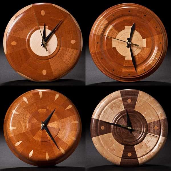
clocks-s.jpg
 
It probably doesn't matter for small works like this, with not much loading on the joints. And John has obviously found it works. Radial grain might be a little stronger, but strongest of all is a brickwork layout with overlapping joints.

"Horizontal" and "vertical" are hard to define here. And there's a third dimension too. With variations in angular orientations, there's at least a zillion combinations, some strong and some weak. If the banding has overlapping contact, it can hold everything together.

With any luck, Malcolm Tibbets will chime in, and have better advice.
 
John These clocks are 2 or 3 layers thick. I use the brick layed alignment for 2 reasons. One is that you are basically gluing end grain to end grain which is not very strong. When you layer the rings you are gluing long grain to long grain which is much stronger. By rotating the next ring 1/2 segment you over lap the weaker end grain joint. This works great on short segments of an inch or so.
Now here's the problem and I may have to wait years to find out. The wood expands and contracts from the center of the clock, out and in. this makes the circle larger and smaller. I made some square based lamps with 45 degree miter joints many years ago. It was from an article in a magazine. After just 2 years the lamps would open up at the narrow end of the joint. This was a long glue joint, maybe 4".
That's part of why I add the plug in the middle. It keeps the joint shorter so wood movement will be less of a problem. The center plug is either segmented or stack layered like plywood. It's also in a tapered groove. I'm hoping that if the outer ring contracts it will just push the inner plug up in the tapered groove.
I've had very good luck with my mirrors but they are only 5 1/2" where these clocks are 8". I'm going to keep the walnut and maple mirror to see how it holds up over the years. Mahagony is a much more stable wood so I think those won't be a problem.
I would also be interested in others opinions on this. Wood movement is a major issue for segmented turners. I've had some blow up so I'm constantly looking for solutions.
Here is where I learned the plywood method. This goblet was built using s solid wood bottom in the goblet cup. It held together fine until it was displayed in a library. The cabinet was glass enclosed with lights. The heat and low humidity made the bottom separate from the sides. I repaired it with a stack laminated piece and then kept it to see how it would hold up over they years. It is still together.
 

Attachments

  • segmented-goblet.jpg
    segmented-goblet.jpg
    11.1 KB · Views: 55
Ok first I did not realize these were layered. Second now that you say that I can only see basically the sides of the top left hand mahagony clock with the maple round center. It looks like the next layer is cut and glued with no overlapping of the joints as you mentioned. It looks like the maple joint is lined up with the mahagony joint in front of it. Maybe if you could post a side photo and show me what you are actually doing that would be great. I am guessing this will be my introduction into segmentation work. I know from building cabinets and other things that wood movement is always a problem and I can see when using dissimilar woods it adds to that problem because they move at different rates. The banding I was talking about was just going to be part of the pie segments and was not overlapping joints with it.

On another note is there a formula for figuring out what the dimensions of each pie peice is to make up a certain diameter clock face.????


While I am at it I have another ???? If I were to run an accent strip between my joints is that another set of problems???? What if I glued my pie shaped pieces up and later came and routed a thin line down the seams and infilled with a decorative strip, would this be better???

Thanks all for the replys. I do not know enough about segmenting yet.
 
John, the clocks by my friend John Lucas illustrate a huge problem regarding wood movement issues. I don't know the size of these, but they may well survive as long as they are small (under 4"). These are essentially segmented platters and platters with wedge-shaped segments forming a central point are risky constructions. In larger sizes, they simply will not survive long-term wood movement. Even in small sizes, they can be quite risky. This is why the number one area of segmented vessel movement problems is the base area. Many segmenters like a pie-shaped base plate for their vessel bases - there are a lot of vessels out there with small cracks in their base plates. When segments form a pie, there’s simply no direction for the wood to move without causing a joint defect. If the wood expands, it can’t move inward, it has to move outward. When it does, the long-grain does not become longer, but the diameter and therefore the circumference become longer. So the only thing that can happen is one of the glue joints is forced slightly open; no glue is capable of stopping the movement. Conversely, if the wood shrinks, it can’t go inward; it has to move outward. The long-grain at the center area does not become longer; therefore a seam towards the center has to open up.:mad::mad::mad:

We, segmenters have been struggling with this issue since the beginning of segmenting. One solution is to create layers that can independently move. This is why “frame and panel†doors are so common (the source of inspiration for my “floating base†technique). When it comes to segmented “plattersâ€, constructing with linear laminations (all wood grain consistently aligned) is the safest method. 🙂
 
Lathe turned clocks Part 2

That Malcolm is just too smart 🙂

From the segmented bowls, platters and vases I have done, Malcolm is right on the money with his explanation of wood movement and segmented turnings. Many of my early turnings do have cracks in the base because I tried to make pie shaped segments. After learning to construct with linear laminations, I have not had one crack.

Greg
 
Linier laminations???? Not quite sure what is meant by this. Can someone post some photos with an explanation??/ So there is no way I can duplicate something like what John is showing that will stand the test of time??? I like the look it has. I must also mention that my clocks will be about 8 to 10 inches in diameter. Also there will be an insert clock movement used and not the motor set up John used so there will be essentially a hole in the center about 4" in diameter. Will this matter in construction???

As I wrote this I was thinking would veneers on top of a solid board do what I want to do???? Or am I still looking at the same problem??? I am asking alot of these questions because of a twofold purpose. I not only want to make some turned clocks but I am also wanting to construct some compass rose patterns and wanted to do them with thicker woods to make an overlay instead of an inlay. I appreciate any help or info anyone can profide.

Thanks again
John T.
 
John, you can definitely construct a clock with segmented rings in an 8" to 10" diameter with a 4" hole in the center. With a 4" center opening, you will only have about a 2" to 3" perimeter and the wood will be able to move slightly inwardly. If you stack several rings as opposed to just using one outside ring, you will increase the stability a lot.

By linear lamination, I'm describing what you might think of when you see a cutting board. The clocks that I posted in the other "clock" thread were turned from linear-laminated strips of wood. If you simply glued strips together and cut out a circle to turn, that would be a linear lamination.

Good luck with your project(s).
 
A photo of the back of a clock

I've been looking at some of the turned pieces on the forum and they are extraordinary. I'm interested in turning a clock with linear glued wood as described in a previous reply. Actually, my wife has been after me to glue up a thick cutting board. I did once and it separated. Maybe I could use part of it for a clock.😉 I would like to see what the back looks like for inletting for the clock mechanism. Thanks.🙂
 
John I'll try to post a photo later tonight of the back. For the segmented clocks I have stacked rings to build up the thickness so I just make the opening in the ring large enough for the clock.
When I do solid clicks I mount the face of the clock on a glue block and then turn an opening large enough for the clock movement. I have 3" and 4" jaws for my chuck so I just turn a slight dovetail rebate to accept the jaws. Then I can mount the clock in reverse to turn the front side.
What I used to do before I had the large jaws was turn the opening and then flatten the back. Then I would drill the proper size hole for the clock movement using a drill chuck in my tailstock. Then put a large piece of wood on a faceplate and flatten it. Use cloth backed double stick tape to stick the clock to the faceplate. To align it I a live center with a cone center that goes in the hole you drilled for the clock movement. This gets is close enough to dead on that you can easily true up the outside and then turn the face of the clock.
 
Thanks for the info, John.🙂 I have some ideas for turning a clock. Will try them and post the results,no matter what.😕
 
Back
Top