• Beware of Counterfeit Woodturning Tools (click here for details)
  • Johnathan Silwones is starting a new AAW chapter, Southern Alleghenies Woodturners, in Johnstown, PA. (click here for details)
  • Congratulations to William Rogers for "Ambrosia Maple Platter" being selected as Turning of the Week for September 16, 2024 (click here for details)
  • Welcome new registering member. Your username must be your real First and Last name (for example: John Doe). "Screen names" and "handles" are not allowed and your registration will be deleted if you don't use your real name. Also, do not use all caps nor all lower case.

First Post: Simple Jigs for Setting Angles with the Oneway Wolverine Grinding Jig

Joined
May 7, 2024
Messages
37
Likes
18
Location
Staatsburg, NY
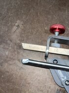
Greetings all. Here is a simple way to set an angle for the Oneway Wolverine Grinding Jig with the platform or the Vari-Grind jig.

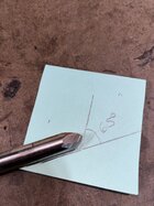
Consider two (transparent) jointed pieces of wood with the same dimensions except one is wider. Place each on with one edge on the platform and then rotate the platform until the opposite parallel edge is tangent with the grinding wheel. The platform will have a lower angle for the wider piece.
Oneway Wolverine Sharpening Jig 1.jpgOneway Wolverine Sharpening Jig 2.jpg
The angle of the bevel ground into a bowl gouge placed on the platform also changes. The wider piece corresponds to a platform angle that produces a larger bevel angle.

There is a relatively simple mathematical relationship between the width of the piece of wood and the bevel angle. If r is the radius of the grinding wheel and A is the bevel angle then the width of the piece of wood is r (1- cos A). So, we can make simple jigs that consist of a jointed piece of wood of various widths to obtain our desired bevel angles for bowl gouges. The jig becomes easier to use if we add a lip to the top edge so that the jig can rest on the wheel and establish the tangency. Still easier for some of us, clamp the jig to the platform so that you can just rotate the platform down until the lip rests on the grinding wheel, tighten the platform clamp, and you have your platform in place.

IMG_9566.jpg
To be continued ... (I attached a PDF with an explanation of the formula.)
 

Attachments

  • Geometry of Wolverine Angle Gauges.pdf
    1.4 MB · Views: 33
Last edited:
Joined
May 7, 2024
Messages
37
Likes
18
Location
Staatsburg, NY
Some notes:

This geometry can also be applied to the Vari-Grind jig. The basic difference is that the piece of wood rests on the top of the gouge in the Vari-Grind jig (instead of the platform) and the tangency to the wheel is created by an arm that extends from the top of the piece of wood parallel to the gouge to the top of the grinding wheel.

Vari-Grind Angle Jig.jpg
This jig works for all settings of the Vari-Grind jig and any length for the protruding gouge. So, for example, you could use it for Ron Brown’s approximation of a 40/40 grind or for long swept-back wings.

The distance of the platform from the grinding wheel does not affect whether this jig works. The angle of the platform will change with the distance, but the resulting bevel angle will always be the same.

Place the jig so that one face is against the grinding wheel. This ensures the correct position of the jig on the platform.

Because you can account for the radius of your grinding wheel, this approach works for composite grinding wheels that get smaller over time. When the radius r gets smaller, the desired jig width does also. So, as your grinding wheel shrinks you can trim your jig to compensate.

If you are very particular about obtaining a specific bevel angle, then you will want to adjust the width of the jig slightly to account for the curvature of the grinding wheel. The width formula, r (1 - cos A), produces the angle A at the heel of the ground bowl gouge. To get closer to the desired overall angle on the nose of the gouge, you want this angle at the middle of the bevel. So, increase the width of the jig by half the thickness of the gouge from the bottom of the flute to the bottom of the gouge. For my ½-inch bowl gouges this is 0.088 inches, or a little more than a sixteenth of an inch and a little less than 3/32 of an inch.

Also, if you are grinding the top of the gouge for the shape of the wings, you probably want to move the angle to the tip of the gouge so that you can then lift the gouge to produce a flat or convex profile and get the desired angle at the tip. That would mean adding the depth of the flute to the width of the jig.

For the Vari-Grind jig application, take into account the depth of the flute by subtracting it from the width.
 
Joined
May 7, 2024
Messages
37
Likes
18
Location
Staatsburg, NY
Here’s a table of angles and widths for an 8-inch grinding wheel (r=4). (Formatting a table correctly seems to be beyond my capabilities. ;))

Angle (degrees)Width (inches)
150.136
200.241
250.375
300.536
350.723
400.936
451.172
501.429
551.706
602.000
652.310
702.632
752.965
803.305
853.651

It’s not something everyone will want to do but it couldn’t be easier to try. I hope some of you do and find it helpful.
 
Joined
Jan 20, 2022
Messages
23
Likes
15
Location
Apple Valley, MN
Paul,
This is helpful, but I do have one question to clear the geomety fog in my brain. In the table and in the diagram with the VariGrind set up, by "width", do you mean the distance from the botton of the gouge to the bottom of the board which is tangent to the wheel? So that would be the sum of the thickness of my gouge and the small spacer board attached to the longer board? So for 45 degrees that sum would be 1.172 inches?
 
Joined
May 7, 2024
Messages
37
Likes
18
Location
Staatsburg, NY
I think the fog cleared Paul. I used the r-M formula, which I should have done first, and for a 45 degree bevel I see the same answer as in your table.
Hey Gary. Thank you for asking about this. It sounds like you have figured it out yourself. I'm tempted to call the formula W = r (1 - cos A), where W is the width, r is the radius of the grinding wheel, and A is the bevel angle, Ruud's Law. ;)

If I can make any of this clearer, I would love to do so. So do please ask for clarification. And let me just add that to center the angle on the middle of the nose of the gouge, rather than at the heel, add about 1/16th of an inch to the spacer block. That will move the gouge down just a hair. Functionally, it won't make an appreciable difference.
 
Last edited:
Joined
Jan 20, 2022
Messages
23
Likes
15
Location
Apple Valley, MN
Hey Gary. Thank you for asking about this. It sounds like you have figured it out yourself. I'm tempted to call the formula W = r (1 - cos A), where W is the width, r is the radius of the grinding wheel, and A is the bevel angle, Ruud's Law. ;)
Thanks Paul. I assumed the longer yellow arrow in one of the diagrams is W
 
Joined
May 7, 2024
Messages
37
Likes
18
Location
Staatsburg, NY
Exactly. Except it's kind of short in the second version for the Vari-Grind, right? (We are talking about the PDF file linked above that contains the explanation of the formula.) The yellow arrows are analogous in the two pictures.
 
Joined
May 7, 2024
Messages
37
Likes
18
Location
Staatsburg, NY
I have been toying with the idea of making an explanatory video. It will take a fair amount of effort for me, because I have not made many videos and a good one requires some planning/thinking. I have the idea of doing Ron Brown's version of the 40/40 grind (which would use both the platform and the Vari-Grind jig) and then putting Sharpie on the bevel of the jig and grinding lightly again on the platform a la Stuart Batty to show how much difference there is. (It's neglible in my experience.)
 
Last edited:
Joined
May 7, 2024
Messages
37
Likes
18
Location
Staatsburg, NY
Angle Gauge Photo 3.jpgAngle Gauge Geometry Photo 1.jpg

For the sake of this thread, here are the photo's that Gary and I were referring to. They come from the PDF file and show the platform and Vari-Grind versions of the geometry that yields the formula. The distance between the parallel blue lines is the width, W, denoted by the yellow line with arrows. The top blue line is a tangency with the top of the grinding wheel and the bottom blue line is the plane of the platform or the bottom of the gouge in the Vari-Grind jig. The green line indicates the angle of the gouge bevel contact with the surface of the grinding wheel (the red circle).
 
Joined
May 7, 2024
Messages
37
Likes
18
Location
Staatsburg, NY
Gary, because you are looking at the Vari-Grind version, I thought I could explain it a little better. As you said, the jig consists of a spacer block and the tangent arm.

IMG_9630.JPG
I found that butting the end of the spacer block (provided that it is square) up against the Vari-Grind jig worked well for getting the orientation with the grinding wheel right.

IMG_9628.JPG IMG_9629.JPG
You are set up when you have the v-arm positioned so that the gouge and the tangent arm both just touch the wheel. I found that keeping the tangent arm on the wheel and moving the v-arm in until the gouge just touches worked well.
 
Last edited:
Joined
May 7, 2024
Messages
37
Likes
18
Location
Staatsburg, NY
It occurred to me that beginners should be alerted that shaping the tip of the gouge with the Vari-Grind jig inevitably increases the angle of the bevel. In that situation, the bevel angle produced on the gouge will be greater than the angle delivered by these jigs. When you grind the tip, you shorten the gouge protrusion and that is what causes the angle to increase. A common approach is to focus grinding with the Vari-Grind jig on shaping the wings and then make a final light pass to blend the tip with the wings.

If you do end up shaping the tip with the Vari-Grind jig, you may want to reset the protrusion to your standard measure (often 1 3/4" or 2") and then make some final passes to recover your bevel angle. You will be removing the heel first and working your way up to the cutting edge. In extreme cases, you will need to repeat this process.

See John Lucas' video for a demonstration of freehand correction of sharpening problems. John isn't using the Vari-Grind jig, so he avoids this creeping of the bevel angle.
 
Joined
Jan 20, 2022
Messages
23
Likes
15
Location
Apple Valley, MN
Gary, because you are looking at the Vari-Grind version, I thought I could explain it a little better. As you said, the jig consists of a spacer block and the tangent arm.

I found that butting the end of the spacer block (provided that it is square) up against the Vari-Grind jig worked well for getting the orientation with the grinding wheel right.

You are set up when you have the v-arm positioned so that the gouge and the tangent arm both just touch the wheel. I found that keeping the tangent arm on the wheel and moving the v-arm in until the gouge just touches worked well.
 
Joined
Jan 20, 2022
Messages
23
Likes
15
Location
Apple Valley, MN
Paul,
You have put a lot of thought and effort into sharing this and a video would be great, however, I can only imagine the time and effort that would require. Eventually I plan using your process but I have experimented with a process I would appreciate your critique on. I have a 1/2 bowl gouge I used for this and the Vari Grind on my 8 inch wheel. I cut a 1/2 inch square piece of wood about 8-10 inches long. On one end I cut a 65 degree bevel. I mounted the wood in the VG just like a gouge with the wood extending 2 inches to the center of the bevel on the wood. I then presented the bevel to my wheel an moved the long V rod until the wood bevel was tangent to the wheel. I replaced the wood with my gouge and ground the bevel and wings as normal. The bevel angle on the gouge measured with my digital gauge was exactly 65 degrees. If this makes sense and is a reasonable process I thought i could cut other bevel angles as needed, If this process works I would use dowels the same diameter as my gouges. Does this process make sense and where will it fail? Thanks.
 

Attachments

  • CECEDC27-AEA5-47E7-855F-DBC873F17865.jpeg
    CECEDC27-AEA5-47E7-855F-DBC873F17865.jpeg
    381.2 KB · Views: 13
  • BFCEA2B3-1E8A-4416-86E3-68DFDC4789B8.jpeg
    BFCEA2B3-1E8A-4416-86E3-68DFDC4789B8.jpeg
    417.1 KB · Views: 11
Joined
May 7, 2024
Messages
37
Likes
18
Location
Staatsburg, NY
Paul,
You have put a lot of thought and effort into sharing this and a video would be great, however, I can only imagine the time and effort that would require. Eventually I plan using your process but I have experimented with a process I would appreciate your critique on. I have a 1/2 bowl gouge I used for this and the Vari Grind on my 8 inch wheel. I cut a 1/2 inch square piece of wood about 8-10 inches long. On one end I cut a 65 degree bevel. I mounted the wood in the VG just like a gouge with the wood extending 2 inches to the center of the bevel on the wood. I then presented the bevel to my wheel an moved the long V rod until the wood bevel was tangent to the wheel. I replaced the wood with my gouge and ground the bevel and wings as normal. The bevel angle on the gouge measured with my digital gauge was exactly 65 degrees. If this makes sense and is a reasonable process I thought i could cut other bevel angles as needed, If this process works I would use dowels the same diameter as my gouges. Does this process make sense and where will it fail? Thanks.
This makes sense! 👍 Would you please start another thread about this and I will comment there? That way we can keep this thread focused on one approach and the new thread focused on yours. And these comments will alert folks to the other thread, too. So, all good.
 
Back
Top