• November Turning Challenge: Puahala Calabash! (click here for details)
  • Sign up for the AAW Forum Pre-Holiday Swap by Monday, November 4th (click here for details)
  • Congratulations to Ted Pelfrey for "Forest Floor" being selected as Turning of the Week for November 4, 2024 (click here for details)
  • Welcome new registering member. Your username must be your real First and Last name (for example: John Doe). "Screen names" and "handles" are not allowed and your registration will be deleted if you don't use your real name. Also, do not use all caps nor all lower case.

CNC Embellishing, 4th Axis, Laser

Joined
Sep 2, 2013
Messages
25
Likes
91
Location
Barrhead, Alberta, Canada
I've been able to successfully combine my CNC with my turnings for embellishment. I still have to work on my creativity like many. The usual problem with applying a CNC to woodturnings are the curves in 2 or more directions. I have used some expensive programs which 'sort of' do this by wrapping a design around the Y axis while using a 4th (or A) axis. This technique works fine for cylinders but comes up very short for a real turned object decoration. With a bowl for example, a laser will lose focus and a router bit will not carve as you want it too if you stray very far from a flat-ish area or rim.

I was inspired by the work of John Lucas with his router platform (recently featured in the AAW magazine), and Jeff Salter with his jig more than a year ago. However I was not happy with either of these approaches for a variety of reasons. I also looked at the very fine work of Bill Ooms and his ornamental lathe approach but I don't have that setup.

There are a variety of Open Software offerings that do similar Y axis image wrapping but once again I was not happy with the limitations of that approach.

Last summer I started more fully exploring a program called Grblgru to use with my CNC. Working with the author, some refinements were made and I am happy to say that I can do pretty much whatever I want to do with any of my turnings now. Best of all this software is Free. In fact you don't even need a CNC to experiment with it, just a Windows computer. The Gcode can be saved easily.

The author originally designed this program to be an educational simulation and added a GCode sender to it as time went on. This can directly operate machines that run on GRBL 1.1 (Arduino Uno) or Grbl-Mega-5X (Arduino Mega 2560) for example. This doesn't work with dedicated Laser burners because they don't work like a regular CNC with a 4th axis. It doesn't work with a Mach 3/4 machine but these could run the generated GCode.
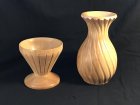
Carved Forms April 2020.jpg
These are two small test forms I made to test Grblgru's ability to follow the curves. As you can see the curves were very well followed. The carving on the left took about 5 minutes, on the right about 10 minutes. Total time to scan a form like this is about 1 to 2 minutes. Since I am an impatient turner this suits me just fine. If I chose to use a laser to burn an image the results are the same. I use a simple 6 watt diode laser which does a more than adequate job of burning into the wood even at half power.

The process is simple: scan the form shape, create a virtual model of it, apply a design and embellish in about 15 min total with practice.
Laser image on bowl surface.jpg

This image I stretched to cover the test curve and left the laser line thick to illustrate how both curves are followed. My 4th axis is a simple one I made using a Nema24 stepper motor, bearings, 8mm shaft and a 1" bolt. My Z axis probe cost me all of a dollar. I take my scroll chuck off the lathe and spin it on to the 4th axis. These things don't have to be expensive and most CNC machines can be used but the owner has to climb a learning curve like anything else. Although ultimately straightforward, this is a method that is best with some understanding of how your CNC really works. This solution is inexpensive and effective in my experience.
 
Joined
Sep 2, 2013
Messages
25
Likes
91
Location
Barrhead, Alberta, Canada
I am not sure how much you know about using a regular 3 axis CNC. I built a very simple Z axis probe, attached it to my control card, in this case a Mega 2560. In Grblgru I activated the probe window, specified the distance and spacing of sample points, and started the probe routine. The machine moves along the X axis, sampling a point on the form every 5mm (in this case). Then points can be spun into a virtual STL model with one click. After that it's up to me to apply a decorative image or write a macro to make the program do something for me.
 
Last edited:
Joined
Sep 2, 2013
Messages
25
Likes
91
Location
Barrhead, Alberta, Canada
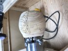
A Z probe does not have to be complicated. They are basically just a switch which, depending on you control board, is normally Open or normally Closed. This is where it is helpful to understand a little more about how your control card and system works. The shot attached shows two very simple probes. The piece of dowel with a pin in it has to contact with aluminum foil attached to the other probe lead. The foil would be stuck to the turned object.

The simple wood block with a switch, two leads to the control board and a spring loaded probe works just fine. I made it from some wire, 4 rivet heads, a pen spring and a simple lever switch. In fact I used that one for the turnings shown above. I don't feel bad when I crash it into something because it's so easy to bend back into shape ;)

Simple Z Probes.jpg

You can always invest in something more expensive and cry when you crash it ha ha.
 
Last edited:

john lucas

AAW Forum Expert
Joined
Apr 26, 2004
Messages
8,477
Likes
4,012
Location
Cookeville, TN
That's pretty cool. Far beyond what my brain can handle. I tried using g a few of the simple drawing programs.a d cant even use those.
 
Joined
Dec 5, 2015
Messages
847
Likes
421
Location
Seattle, WA
Jeff, interesting stuff. I like your inexpensive approach with the DIY probe and 4th axis. Sometimes times when talking CNC with woodturners their resistance comes down to them not being able to afford it. These same people have no hesitation buying $4K+ lathes. IMO it's more the learning curve that's the hesitation to CNC.

Even though I've been doing this sort of stuff for years I'm not quite following what you've done here. Your first picture shows 2 pieces you hand turned, probed and CNC fluted, correct? The left piece is easy, that involves indexing and a flute cut without rotation of the piece during fluting. That could be done without CNC.

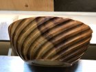
The piece on the right is more complicated having 4th axis rotation while fluting. You probed the turned piece to establish the contour. Maybe it's just the photo perspective, but it doesn't look to me that the cutter exactly followed the contour. The cut depth seems to vary from the actual contour being less deep in the necked down area than at the bottom and top. How was that done, in CAD or in Grblgru?

Watching the Grblgru author's video of the egg bot machine simulation he shows only marking spheres and egg shaped pieces. Could the laser marking on your egg shaped piece be done on your right hand piece in your first picture since that piece has both concave and convex contour?
Will Autodesk's Fusion 360 do marking on parts like yours or does it only wrap on simple cylindrical parts? I've only looked briefly at Fusion and never spent the time needed to use it.

Have you done turnings totally on the CNC rather than hand turning? My turnings are done on the CNC so no contour probing is needed for embellishment.

Because I did CNC'ing primarily in metal and plastics for a living I own high dollar software and machinery. My CNC wood cutting has been mostly in retirement although I did have a couple artist customers where I did their art on the CNC's. When I sold the business a couple machines were kept for fun stuff.
 
Joined
Sep 2, 2013
Messages
25
Likes
91
Location
Barrhead, Alberta, Canada
Hi Doug. I agree price is a barrier for most except when it comes to a decent lathe. I enjoy building stuff so I have made a few CNCs now with 3 different styles. Many of the commercial CAD offerings I have looked at either don't do what Grblgru can do in this case, or are waaaay expensive. Since the program is free and the simulator accurate, a person can play with it and make all kinds of mistakes with no harm done.

Either of these pieces could be done without a CNC but I am too impatient to take a ton of time to do it correctly. As you observed, the fluted vase has slightly less depth to the flutes at the neck than at the top and bottom - a matter of a few tenths of a mm. This was not intentional but since the result looked attractive I didn't bother correcting it. I may have had a slight scan error since it was originally intended to be a test piece and I scanned it quickly.

Macro Method: In the case of flutes, after scanning a piece I take the data points and import them into a spreadsheet I made. There are several possibilities that come out of that including straight flutes, spirals, curved flutes etc. I am only limited by my imagination. With the cup form above I commented out parts of the plot line to just allow the CNC to cut where I wanted it. This took less than a minute to do then I could preview the result in Grblgru to see if the CNC would move as I want it too. I can do a 'trial run' by having the Z stay a few mm above the workpiece and watch from the side to see if the motion and clearance is what I want, then lower the Z as necessary. If it's not correct, stop the run, go back to Origin and start again. Since I am working with degrees of rotation I make sure it all adds up to 360 so the pattern is even.

A piece like this one is only about 15 lines of code plus the coordinate points which I copy/paste into the macro. This was my first crack at this method and worked out pretty well. I did something similar with a 1/8" endmill and pierced through the side completely with a series of arcs - took about 5 min... way faster and more accurate than by hand.

Fluted Bowl 2.jpg

Image Projection Method: This way is Much easier. I can apply a DXF, SVG or BMP file to the scanned/created STL of a piece in Grblgru. In the process of setting up a Job the image can be sized, rotated, moved around etc. The result can be run in the Simulator to see how it will turn out. This can be either laser or Router or pen as you wish. Grblgru will follow the curve plot as it was scanned in and apply the design using XA and Z, ignoring the Y. I could apply the celtic design above to the vase shape easily but it wouldn't look so great so a different design might be better ;).
 
Last edited:
Joined
Sep 2, 2013
Messages
25
Likes
91
Location
Barrhead, Alberta, Canada
As far as using a CNC to make a bowl, vase, etc I agree it could be done, but I really enjoy woodturning. Making a bowl or plate on a lathe is much faster than with a hobby CNC. There is more artistic freedom, design opportunities and better surface finish as well I think. So turning a form, carving a design on it with a CNC in a few minutes works for me. A 'best of both worlds' scenario. I don't sell the stuff so I am free to make whatever I want.

Also, as you know, a CNC is a very versatile tool to have in a shop once you climb the learning curve like anything else. I have made all kinds of things with mine aside from this application. A nice challenge in retirement.

I have Fusion 360 and appreciate the use of it but I have not tried any of this with it so I can't comment on that. Too many programs to learn all at once lol
 

RichColvin

Super Moderator
Staff member
OTI Member
Joined
Mar 13, 2016
Messages
689
Likes
587
Location
Marysville, OH
Website
www.colvintools.com
If you enjoy these forms, you should look into ornamental turning. I put together a web site to introduce the craft to those new to it. The link is below : the Ornamental Turning Book of Knowledge.
 
Joined
Sep 2, 2013
Messages
25
Likes
91
Location
Barrhead, Alberta, Canada
Thank you for the site information. I have long looked at ornamental turnings and considered them. I think I may be able to copy some of the patterns with my current setup eventually. I have recently been considering how I might implement a fishscale pattern on a form. I have Bill Ooms program on a Mac and have played with it a little. I haven't built an ornamental lathe type cutter yet as I don't have much access to metal working machinery. I have also looked at the MDF ornamental lathe and seen one in action. I did acquire a RS3000 at Portland in the silent auction and have played with that. Sadly it prefers very hard woods and side grain but otherwise seems to make interesting marks. This would be avoided with a Router + CNC combo so I may reproduce those patterns in time too.
 

RichColvin

Super Moderator
Staff member
OTI Member
Joined
Mar 13, 2016
Messages
689
Likes
587
Location
Marysville, OH
Website
www.colvintools.com
I have it on good authority that the MDF rose engine lathe kit is going to be available again soon.
 
Joined
Dec 5, 2015
Messages
847
Likes
421
Location
Seattle, WA
Jeff, we may be similar in our ways of programming. I use my Centroid control's macro language to program frequently. That way I can get a very short Gcode file that's easy to modify the program. For instance: your bowl shown 4 posts back. I could program the cutter path for the flutes easier than I could drawn a 3D model of it. If I did have a 3D model using my CAM software it'd generate a humongous long program.

I understand what you're saying about your home build machine not being rigid enough to do complete turnings on it. My machine weighs about 2-1/2 tons, it'll do turnings much faster than most any hand turner could with surfaces needing very little sanding..
 
Joined
Sep 2, 2013
Messages
25
Likes
91
Location
Barrhead, Alberta, Canada
A macro is certainly the way to go for a predictable thing like an arc, line or spiral. They are quite easy to write even for a newbie like me. I struggled with getting a decent Sine wave until Grblgru suggested I just import a DXF of one, create a Job, and take what I wanted from the generated GCode. He was right. It is very easy to let the computer do all the math work, lol, not my strong suit...

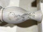
A question was asked above about following curves. I turned a quick test vase this afternoon and burned this little fellow onto it. The diode laser I use stayed properly in focus 57mm above the surface with the Z moving up and down as appropriate. Any lack of smoothness to the lines is because of the original image, not the machine. It is a test after all. The first image is the 'plan'. The imported DXF floats above the vase STL and the projected image can be seen on the surface.

Lizard on Vase Projection.jpg

The second image is the laser burn. It took about 5 min as I wasn't in a hurry and was experimenting some more with power and speed settings for the laser.

Lizard on Vase2.jpg

The little fellow curves into the vase neck and around the sides to illustrate curve following better than the first image I think. The darker area at the top is because the wood is a little darker there of course. I hope that answers any questions about curve following.
 
Joined
Dec 5, 2015
Messages
847
Likes
421
Location
Seattle, WA
Very nice Jeff. Makes me want to go right out to the shop and make something..except for the fact we're tearing down my at home shop to rebuild bigger and better.

I have a book of Celtic designs similar to that one. Sometimes I color them in with fine tipped acrylic pens for effect.
 
Joined
May 9, 2019
Messages
67
Likes
31
Location
Fairlawn, Virginia
Jeff - I was able to to do some tests on my Shopbot CNC and figured a way for this to work for me. The Shopbot software has a built in probe routine which allows me to select either normally open or normally closed. It will create a 2D polyline DXF that I can easily import into my design software which is Vectric Aspire. I just used a steel dowel pin in my collet, then wrapped my piece to be probed in aluminum foil. I then attached a jumper wire from the foil to the input on my control board. In the normally open mode, this closes the ground path when it touches the foil and gives me an input. In my test, I selected one diameter to measure and compare, it came within .005" in my design software after probing. Thanks for turning me on to this technique!
 
Joined
Sep 2, 2013
Messages
25
Likes
91
Location
Barrhead, Alberta, Canada
Hi Brad. I used to use that approach with Estlcam but abandoned it in favour of Grblgru and a simple Z axis probe. The Z Probe is a simple idea as you have discovered - just a switch - so the aluminum foil and contact pin works well. My second Z probe is slightly more compact than my first and I put it in the router chuck to avoid offsets.
 
Joined
Sep 2, 2013
Messages
25
Likes
91
Location
Barrhead, Alberta, Canada
I have made progress with Bill Ooms' COrnlathe software and embellishing my turnings. The problem was understanding how I could get Grblgru and COrnlathe to work together. With help from Bill, I was able to understand his data format requirements and do this manually. I have since been in email discussions with Grblgru's author and he has made a Export to COrnlathe function that works really well. Now I can Z probe a piece like a vase or bowl, export it to COrnlathe and go from there. A friend complied a Windows version of Bill's program so I can just use one computer instead of two. It has been fun exploring COrnlathe's possibilities and adapting them to my CNC with a 4th axis. I am able to rotate my 4th axis 90 degrees so it can be horizontal or vertical. I can use endmills or slot cutting type bits to achieve several types of designs that will work with the CNC. I can export the GCode from Bill's program and with a couple minutes of axis name/speed work in Notepad++, it will work fine in Grblgru. Grblgru is trying to automate that process as well so there could be an Import from COrnlathe function pretty soon.
Basket and Vase.jpg

These turned out pretty well. They are all Birch. I turned them on the woodlathe, then embellished with the CNC, and returned to the lathe for a little sanding and base work. I leave the pieces in the scroll chuck and just move them from machine to machine that way. It only took about 5 to 15 minutes or so to embellish each one so for an impatient turner like me that's perfect lol. I am still learning about finishing techniques for this kind of embellishment. It's all part of the learning curve.
 
Joined
Sep 2, 2013
Messages
25
Likes
91
Location
Barrhead, Alberta, Canada
I can report that Grblgru can now be used to Scan a turning in the 4th axis, Export the correct file to COrnlathe, and Import the GCode generated by COrnlathe to be used on that turning. The piece turned can be in a Vertical orientation so the side or top can be embellished, or in a Horizontal orientation to do the side or end. With this capability I can do the side of bowls or vases with endmills or slotcutters for example as appropriate to the pattern. I can decorate endgrain coasters with a pointed slot cutting bit easily. I can decorate a box top with an endmill easily too.
 
Back
Top