In an earlier article, I described a simple no-math, no-cost method of determining where to make the straight cuts needed to transform a wooden cylinder into first an eight-faceted approximation to a sphere and then, optionally, into sixteen-faceted and higher-order approximations to a sphere. The original concept seems to have been discovered independently by Soren Berger and Al Hockenbery several years ago and they have promoted it widely. My modest contribution was to show how to mark up the work piece for cutting without the need for any calibrated calipers or any calculations. In fact, you do not need a ruler of any kind, only a set of adjustable calipers and a simple design graph that I showed how to draw.
Later, it occurred to me that this overall procedure ought to applicable to spheroids as well as spheres. (Oblate spheroids are spheres that are compressed along the spin axis; prolate spheroids are spheres that are stretched along the spin axis.) After a bit of analysis, I found that, indeed, the procedure is applicable, with some simple revisions, for 8-sided and 16-sided approximations. To me, this is nice, because I turn several globe-and-finial type Christmas ornaments every year and prefer the oblate spheroid shape for the globes.
The following figures show the sequence of mark-and-cut operations that lead first to an 8-sided and then a 16-sided approximation of an oblate spheroid whose length is 2 inches and whose diameter is 3 inches. The final result after trimming by eye and sanding is shown also. The last figure is a design graph that is generally similar to the ones that I posted earlier for spheres and which is still useful for spheres as well as spheroids. The main changes are that I have re-labeled some of the lines and added one more line. Specifically: The old lines A, B, and C, which gave the offsets for marking the cut lines in Stages 1, 2 and 3, have been re-labeled A1, A2 and A3. The new line, labeled B2, is needed only in Stage 2 for non-spheres. Finally, the line previously marked D is now marked DLH for reasons that will be apparent later. This example produces an oblate spheroid. If the length L of the starting cylinder is made larger than the diameter D, this same procedure will produce a prolate spheroid.
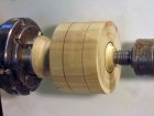
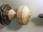
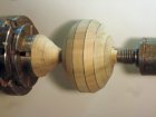
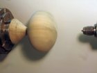
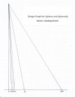
Here is how it all works. First prepare a cylinder with the desired diameter D and length L of the intended spheroid. The cuts defining the ends of the cylinder need to be deep enough to allow the necessary marking of the ends at each stage. Next, measure and “save” three parameters of the prepared cylinder using calipers. Each measurement is “saved” by laying the calipers horizontally on the chart and moving them down until they exactly span the distance between the R line and the DLH line. A pencil tick at that point next to the R line will record that position. The three measurements are the diameter D of the cylinder, the length L of the cylinder, and the diagonal H of the cylinder. The What? As you look at the cylinder, its outline is a rectangle. We need to measure the diagonal of that rectangle. Put one leg of the caliper at top dead center of one end of the cylinder and put the other leg at bottom center of the other end and “save” the result. Note that the last measurement must be made before further cutting begins.
For Stage 1, we need to measure outward in both directions from the top corners of the apparent rectangle that frames the starting cylinder and make cutting lines as shown in the first figure. For the horizontal legs, the required offset is A1(L). This means the distance from line R to line A1 at the level on the graph where we marked to save the value of L. For the radial offsets along the ends of the cylinder, the required offset is A1(D).
After turning off the corners of the rectangle with straight cuts, we are left with an approximation whose profile looks like a squashed octagon, as shown in the second figure. If desired, one can refine the approximation by proceeding with Stage 2. In Stage 2 we again will mark cut lines on both sides of each of the upper corners of the newly created figure.
The rules for selecting the various offsets to use are slightly more complicated but not burdensome. Here they are:
1. If the offset is in a horizontal direction use A2(L).
2. If the offset is in a radial direction (across an end) use A2(D).
3. If the offset is along a slant, use B2(H).
Actually, the choice is almost intuitive; you use L when measuring in the L direction, D when measuring in the direction that D measures, and H when measuring along a path that depends on both L and D. The result of making these cuts is seen in the fourth figure. It may be practical to take this process to a third stage and produce a 32-sided approximation to a spheroid, but I have not worked out the details yet.
There you have it—the only game in town for hobbyists and semi-pros when it comes to assistance in turning spheroids. Spheroid-cutting jigs are feasible but would be much more expensive than the present sphere-cutting jigs, and although CNC systems can do almost anything, they tend to be beyond the reach of most of us.
The design graph shown is most easily obtained by doing a screen print, or by dragging the image off onto the Desktop and printing the resulting file. The result usually will be a slightly smaller version of the above figure, which will not affect its usefulness. For those who cannot easily copy the figure, here is how to roll your own: Obtain a piece of quadrille paper (any kind will do). Draw a vertical line R from near the top left corner of the page down to near the bottom of the page as shown in the figure above. The exact length of R does not matter. Draw a horizontal baseline from R most of the way across the page. Along this base line, carefully mark ticks at the following positions, measured in inches from line R: DLH = 6.00, A1 = 1.76 (1-3/4), A2 = 0.646 (21/32), B2 = 0.457 (29/64), A3 = 0.301 (19/64). All of these are presented here in more precision than really is needed for practical purposes. Finally, carefully draw slanted lines from the top of the Reference line to each of points just marked along the base line.
Below is an abbreviated step-by-step procedure for turning spheres or spheroids. I would suggest that those interested print a copy of this procedure and a copy of the design chart and slip them back to back into a plastic sheet protector. The latter are available in most stationery stores and will protect this data in a shop environment.

Later, it occurred to me that this overall procedure ought to applicable to spheroids as well as spheres. (Oblate spheroids are spheres that are compressed along the spin axis; prolate spheroids are spheres that are stretched along the spin axis.) After a bit of analysis, I found that, indeed, the procedure is applicable, with some simple revisions, for 8-sided and 16-sided approximations. To me, this is nice, because I turn several globe-and-finial type Christmas ornaments every year and prefer the oblate spheroid shape for the globes.
The following figures show the sequence of mark-and-cut operations that lead first to an 8-sided and then a 16-sided approximation of an oblate spheroid whose length is 2 inches and whose diameter is 3 inches. The final result after trimming by eye and sanding is shown also. The last figure is a design graph that is generally similar to the ones that I posted earlier for spheres and which is still useful for spheres as well as spheroids. The main changes are that I have re-labeled some of the lines and added one more line. Specifically: The old lines A, B, and C, which gave the offsets for marking the cut lines in Stages 1, 2 and 3, have been re-labeled A1, A2 and A3. The new line, labeled B2, is needed only in Stage 2 for non-spheres. Finally, the line previously marked D is now marked DLH for reasons that will be apparent later. This example produces an oblate spheroid. If the length L of the starting cylinder is made larger than the diameter D, this same procedure will produce a prolate spheroid.


Here is how it all works. First prepare a cylinder with the desired diameter D and length L of the intended spheroid. The cuts defining the ends of the cylinder need to be deep enough to allow the necessary marking of the ends at each stage. Next, measure and “save” three parameters of the prepared cylinder using calipers. Each measurement is “saved” by laying the calipers horizontally on the chart and moving them down until they exactly span the distance between the R line and the DLH line. A pencil tick at that point next to the R line will record that position. The three measurements are the diameter D of the cylinder, the length L of the cylinder, and the diagonal H of the cylinder. The What? As you look at the cylinder, its outline is a rectangle. We need to measure the diagonal of that rectangle. Put one leg of the caliper at top dead center of one end of the cylinder and put the other leg at bottom center of the other end and “save” the result. Note that the last measurement must be made before further cutting begins.
For Stage 1, we need to measure outward in both directions from the top corners of the apparent rectangle that frames the starting cylinder and make cutting lines as shown in the first figure. For the horizontal legs, the required offset is A1(L). This means the distance from line R to line A1 at the level on the graph where we marked to save the value of L. For the radial offsets along the ends of the cylinder, the required offset is A1(D).
After turning off the corners of the rectangle with straight cuts, we are left with an approximation whose profile looks like a squashed octagon, as shown in the second figure. If desired, one can refine the approximation by proceeding with Stage 2. In Stage 2 we again will mark cut lines on both sides of each of the upper corners of the newly created figure.
The rules for selecting the various offsets to use are slightly more complicated but not burdensome. Here they are:
1. If the offset is in a horizontal direction use A2(L).
2. If the offset is in a radial direction (across an end) use A2(D).
3. If the offset is along a slant, use B2(H).
Actually, the choice is almost intuitive; you use L when measuring in the L direction, D when measuring in the direction that D measures, and H when measuring along a path that depends on both L and D. The result of making these cuts is seen in the fourth figure. It may be practical to take this process to a third stage and produce a 32-sided approximation to a spheroid, but I have not worked out the details yet.
There you have it—the only game in town for hobbyists and semi-pros when it comes to assistance in turning spheroids. Spheroid-cutting jigs are feasible but would be much more expensive than the present sphere-cutting jigs, and although CNC systems can do almost anything, they tend to be beyond the reach of most of us.
The design graph shown is most easily obtained by doing a screen print, or by dragging the image off onto the Desktop and printing the resulting file. The result usually will be a slightly smaller version of the above figure, which will not affect its usefulness. For those who cannot easily copy the figure, here is how to roll your own: Obtain a piece of quadrille paper (any kind will do). Draw a vertical line R from near the top left corner of the page down to near the bottom of the page as shown in the figure above. The exact length of R does not matter. Draw a horizontal baseline from R most of the way across the page. Along this base line, carefully mark ticks at the following positions, measured in inches from line R: DLH = 6.00, A1 = 1.76 (1-3/4), A2 = 0.646 (21/32), B2 = 0.457 (29/64), A3 = 0.301 (19/64). All of these are presented here in more precision than really is needed for practical purposes. Finally, carefully draw slanted lines from the top of the Reference line to each of points just marked along the base line.
Below is an abbreviated step-by-step procedure for turning spheres or spheroids. I would suggest that those interested print a copy of this procedure and a copy of the design chart and slip them back to back into a plastic sheet protector. The latter are available in most stationery stores and will protect this data in a shop environment.

