• We just finished moving the forums to a new hosting server. It looks like everything is functioning correctly but if you find a problem please report it in the Forum Technical Support Forum (click here) or email us at forum_moderator AT aawforum.org. Thanks!
  • Beware of Counterfeit Woodturning Tools (click here for details)
  • Johnathan Silwones is starting a new AAW chapter, Southern Alleghenies Woodturners, in Johnstown, PA. (click here for details)
  • Congratulations to Dave Roberts for "2 Hats" being selected as Turning of the Week for April 22, 2024 (click here for details)
  • Welcome new registering member. Your username must be your real First and Last name (for example: John Doe). "Screen names" and "handles" are not allowed and your registration will be deleted if you don't use your real name. Also, do not use all caps nor all lower case.

What should I call this?

Joined
Apr 17, 2012
Messages
12
Likes
0
Location
Chicago
Hi all,

I decided a while back that I'd like a bowl lathe to accompany my powermatic 90. I did some searching, and decided that the available options were very nice and very expensive. Plus, I kinda wanted something that would look appropriate sitting next to my pm90.

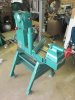
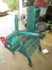
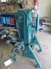
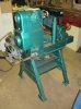
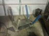
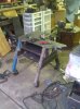
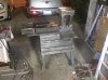
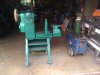
So, I decided to build my own. It's taken me a few months, and I've had to pick up a few new skills along the way (e.g. welding), but the bowl lathe is now functional! It still needs a little prettying up (a guard for the jackshaft, the tailstock riser, and some repainting), but it's up and running, weighs more than I can lift, and is solid as a rock!

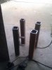
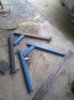
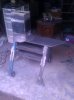
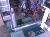
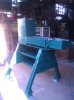
The lathe is built around a pm90 headstock that would otherwise have been scrapped. The bed ways were actually made by Jeff Nicol for a different project, and they sit 17" below the spindle for a 34" swing. The tailstock is from a sebastian metal lathe. The rest of the base, risers and banjo are all scrap metal welded together and painted an eye-popping powermatic green :) The legs are splayed at 45 degrees and the stance is 2 feet wide.

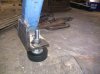
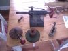
The motor is a 2hp 3ph TEFC explosion-proof number salvaged from the scrapyard for $12, and it's run by a 2hp VFD. At full speed, the big pulley on the jackshaft gives me 300rpm - 1200rpm using the reeves drive, and the small pulley gives me 700rpm - 2800rpm. The VFD brings the speed down to zero as needed.

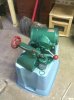
I've attached a few pictures of the build, and links to a couple of youtube videos showing the first run. The test piece is a 13" maple platter blank, 3" thick. It's mounted a little off-centre, and wobbles a good bit. The second video shows it spinning at 2500rpm (not recommended!), and the lathe doesn't budge a bit. Happy!

I haven't mounted anything bigger, or actually turned anything on it yet - a crazy work schedule and a new baby have kept me busy the last few weeks! Looking forward to giving it a proper trial run :)

Sorry for the long post - hopefully some of you find this as interesting as I do :)

Edit: So, what should I call it? I'm thinking maybe "PM92" ?

Best,

Lee
 
Last edited:
Joined
Apr 17, 2012
Messages
12
Likes
0
Location
Chicago
Build pics

More pics of the build:
 

Attachments

  • IMG_20130430_072941.jpg
    IMG_20130430_072941.jpg
    113.8 KB · Views: 73
  • IMG_20130430_073006 (1).jpg
    IMG_20130430_073006 (1).jpg
    119.4 KB · Views: 74
  • IMG_20130511_213357.jpg
    IMG_20130511_213357.jpg
    108.7 KB · Views: 73
  • IMG_20130512_225516.jpg
    IMG_20130512_225516.jpg
    110.6 KB · Views: 73
  • IMG_20130515_200327.jpg
    IMG_20130515_200327.jpg
    117.8 KB · Views: 82
Joined
Apr 17, 2012
Messages
12
Likes
0
Location
Chicago
And some more:

Thanks for looking!
 

Attachments

  • IMG_20130516_210330.jpg
    IMG_20130516_210330.jpg
    109 KB · Views: 84
  • IMG_20130522_140114.jpg
    IMG_20130522_140114.jpg
    112.5 KB · Views: 82
  • IMG_20130525_115139.jpg
    IMG_20130525_115139.jpg
    107.5 KB · Views: 84
  • Painted bits.jpg
    Painted bits.jpg
    66.7 KB · Views: 91
  • unpainted banjo.jpg
    unpainted banjo.jpg
    71.4 KB · Views: 91
Joined
Dec 10, 2006
Messages
578
Likes
7
Location
Mesa, Arizona
Very cool!

From the video, it looks like the lathe will be very smooth and will have plenty of capacity. Well done!
 

Dennis J Gooding

Beta Tester
Beta Tester
Joined
Apr 10, 2010
Messages
827
Likes
746
Location
Grants Pass, Oregon
Very good workmanship there Leo. Congratulations. My only concern is that the stance both lengthwise and crosswise may be a tad small if you mount unbalanced pieces of size near the max capacity of the lathe. The center of gravity of the system with a large bowl blank mounted is going to be quite high. Try it out cautiously before you challenge it. You may want to add rails under the present feet to get a larger footprint.

Dennis
 

odie

TOTW Team
Joined
Dec 22, 2006
Messages
7,116
Likes
9,812
Location
Panning for Montana gold, with Betsy, the mule!
Very good workmanship there Leo. Congratulations. My only concern is that the stance both lengthwise and crosswise may be a tad small if you mount unbalanced pieces of size near the max capacity of the lathe. The center of gravity of the system with a large bowl blank mounted is going to be quite high. Try it out cautiously before you challenge it. You may want to add rails under the present feet to get a larger footprint.

Dennis

I was thinking the same thoughts as Dennis......

Looks like a terrific job nonetheless.....:cool2:

ooc
 
Joined
Apr 17, 2012
Messages
12
Likes
0
Location
Chicago
Hi everyone,

Thanks for the nice comments. I'm really pleased with how it's turning out :)

Dennis and Odie: I share your thoughts on the width of the stance. When I started, I based the rough dimensions for the stance on the Robust AB, but have since realized that the larger riser does make the centre of gravity much higher. If I mount a piece at the limit of the 34" capacity, it'll only be 7" narrower than the width of the feet at front and back. For sure, I'll be running the VFD close to zero rpm when I fire it up for the first time! It wouldn't be too much trouble to weld some angle iron across the bottom of the feet if needed to widen the stance (other than straining my 500lb-rated hoist!). In truth, I doubt I'll be getting close to the max capacity very often. But it's nice to have it available :)

Nick: That's a great question. I'd been pondering it in my head, but hadn't tallied anything up until you asked. So, here are the rough estimates from memory.

Headstock $100
Bearings $30
Tailstock $25
Bed ways $100 (Thanks Jeff and Mike!)
Motor $12
Motor bearings $20
Scrap metal $100
Hockey Pucks $10
Misc Hardware $30
Primer/Paint $20
Jackshaft $20
Pulleys $35
Pillow blocks $25
Belts $60
Plug/wiring $16
VFD/controls used existing

Total $603

Now, I haven't factored in shipping costs for any of the parts, which were considerable and probably add at least another $200 to the total (shipping for the headstock alone was $70). But, I figure if I bought a PM3520 I'd be paying some big shipping costs too, so it helps me justify leaving it out :)

I also didn't include things like consumable costs e.g. welding wire was about $50. Figure that goes with any build.

In terms of hours in this thing? No idea. Lots. Several months worth of grabbing a few hours here and there, and a good dose of reading about similar projects too. Doesn't matter to me really, as I realized very quickly after starting the project that my main motivation to complete it was for the fun of the build rather than cost savings. But, as it stands I think the overall cost was under $900 including shipping costs and consumables. The project would have been about $250 cheaper if I hadn't decided to use a pm90 headstock with Reeves drive (using pillow blocks and simple step pulleys instead). But, I wanted myself a sister for my pm90 :)

Hope this helps anyone contemplating a similar project!

Lee
 
Joined
Mar 20, 2009
Messages
207
Likes
1
Nah... She's a Lady, man!

Great looking lathe. Could you post a pic straight on from the front with the tail stock on the lathe. Thanks.
You could call her Lady-go-turna. Or if you really want to play with peoples minds just call her Pinky.
 
Joined
Sep 10, 2010
Messages
148
Likes
0
Location
Stow,Ohio
LA BALL Lee Alkureishi Big A_ _ Little Lathe
A s h
Just having fun,couldn't think of any other name.
It is a very nice lathe I think it's going to be a good lathe for the big stuff.
 
Joined
Apr 17, 2012
Messages
12
Likes
0
Location
Chicago
Bart,

I'll try to get that pic for you, but have been basically living at work this week! I haven't made the riser for the tailstock yet, so the centers don't quite line up yet - they're off by about 11"!

Odie, that's a great question, and one that I've been pondering too. I'm definitely no machinist, so getting things perfectly square to within 0.005" isn't my forte... With the headstock, the riser warped significantly from the welding heat, and I had to do a fair amount of work with the angle grinder to get it close again. It's not perfect, but close enough.

I used adjustable riser mounts for the bed ways (4 sets of nuts & bolts), so the ways can be adjusted in any dimension to parallel the axis of the spindle. That way, as long as the tailstock riser is square, it'll line up with the spindle. It'll be a pain in the behind to line this up the first time around, but after that hopefully it should stay locked down..

In terms of building the riser, I'm definitely open to suggestions. I have some plate steel for the base and top of the riser, and will probably take another trip to the scrapyard for something suitable for the back and sides (Either heavy plate, or steel tubes with thin plate cladding). Front will be left open (at least the lower portion) to allow for a locking mechanism. The tailstock itself will probably lock down to the top of the riser using the existing locking mechanism.

I have no doubt it won't line up perfectly first time around - I'll likely need to shim it to some extent, but that should be relatively easy since it'll be removable from the top of the riser.

Again, suggestions are always welcome!

Lee
 
Joined
Mar 20, 2009
Messages
207
Likes
1
Lee when you did the welding on the head did you stitch weld it. In other words weld an inch to an inch & a half & then skip the same space & then weld again in the same manner going around the base then go back & fill in the empty spaces. I would have started by tacking welding the base in the middle of the length on both sides & then did the skip pattern weld each way out from the middle alternating sides. This would have helped to minimize the warping.

Which method & welding medium did you use. Did you bolt the head to the steel & then weld the steel to the base?

What about using a double ended Morse taper to align the head & tail stock & shimming the tail stock up until it is properly positioned to take your measurement. I think I would use square tube & just cut out a opening on the bottom front or back edge for access for the wrench to lock it down. You may not need a wrench of you weld a rod or bar stock to the nut it would always be there. Also if you design a cam lock you could put the lock lever on the back side.
 
Last edited:
Joined
Apr 17, 2012
Messages
12
Likes
0
Location
Chicago
John, I couldn't agree more :)

Bart: I didn't stitch weld it, but read about that later when figuring out why it warped so much. Did I mention this was my first welding/metalwork project? :cool2:

For the headstock, I welded the riser to the base first, then used an angle grinder to rough-level the top surface. I then drilled 2 holes for the headstock bolts, and bolted it down to the riser. The spindle is more-or-less parallel to the ways, but I'll need to fab a jig of some sort to get it perfectly aligned before I try to line up the tailstock. I had thought of a double-ended morse taper, but I'm not sure it's worth the cost for something that I'll likely only use once. The nice thing about the tailstock is that it has 6" of travel, so I'll be able to check alignment at 2 spots on the bed 6" apart - should be accurate enough for most needs.

I used a 115V lincoln flux core welder with 0.035" flux core wire. I was worried that the penetration wouldn't be adequate with my wee welder, so I bevelled all the edges and used multiple passes for the thicker parts. Even so, I asked a pro welder to check it when I was done. He said it looked fine. Even so, I'll be taking it *VERY* easy to start with. I probably put way more weld bead on this thing than was strictly necessary (about 4lbs of wire, all told), but I don't want the headstock and a 200lb piece of wood coming off any time soon!

Some nice ideas for the tailstock riser - thanks! A lot of it will come down to what I can find for materials - one of my goals was to do as much from scrap metal as possible. I made a cam lock for the banjo, and it was fairly straightforward to do - definitely an option.

Best,

Lee
 
Back
Top