• Beware of Counterfeit Woodturning Tools (click here for details)
  • Johnathan Silwones is starting a new AAW chapter, Southern Alleghenies Woodturners, in Johnstown, PA. (click here for details)
  • Congratulations to Dave Roberts for "2 Hats" being selected as Turning of the Week for April 22, 2024 (click here for details)
  • Welcome new registering member. Your username must be your real First and Last name (for example: John Doe). "Screen names" and "handles" are not allowed and your registration will be deleted if you don't use your real name. Also, do not use all caps nor all lower case.

3520 Swing Arm w/ Variable Speed

Joined
Sep 30, 2008
Messages
43
Likes
0
Location
Charlotte, NC
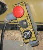
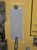
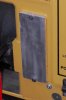
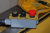
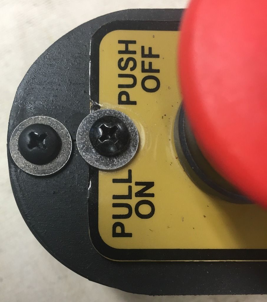
Powermatic offers the "remote switch" (which I have) for the PM3520 lathe. It's a nice option, but only provides a power "on" or "off" option. I am thinking it would be REALLY nice to have the variable speed on the remote switch as well ... so maybe I'll make a swing arm like the Oneway offers.

2436_lathe_350px[1].jpg

Here's my questions ...

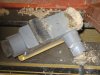
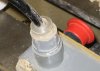
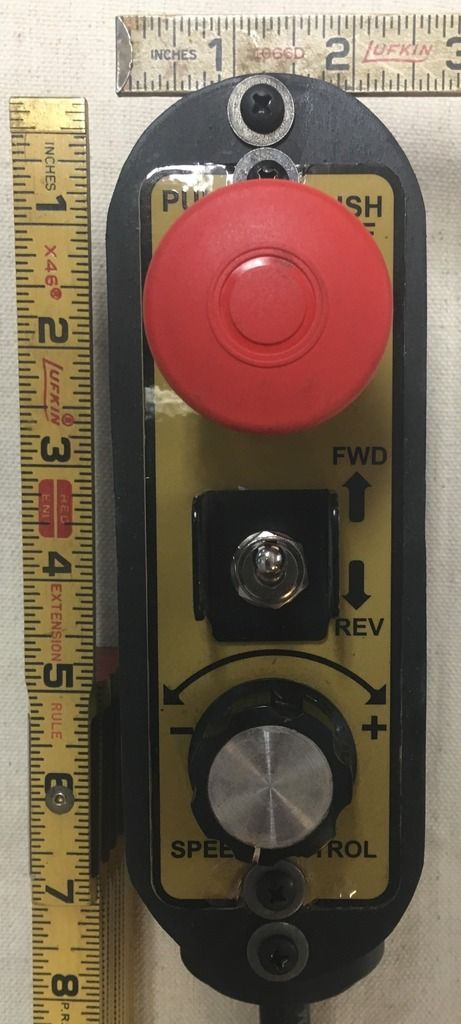
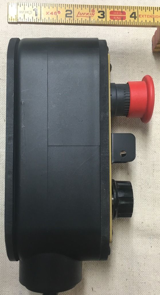
- Does anyone know what parts would be needed for the variable speed component to make another control out on an arm?

- I'm thinking two layers of variable speed (one on the head stock and one on the arm) might be problematic as they would conflict/compete with each other. Would they really? I suppose if they would a toggle could be put on the arm to make it a master (??)


This is just a hair-brained idea right now ... anyone else tried this? I don't know enough about the electric side of things so I figured I'd stir up the conversation around here.
 
Last edited:
Joined
May 14, 2005
Messages
75
Likes
0
Location
Kennebunkport, Maine, USA
Website
www.mainebowls.com
Here's my attempt

Jeremy, I read someone else's post somewhere for making a remote switch for the Jet similar to the Powermatic and decided to give the concept a try. After unscrewing the switch faceplate and labeling the wires, I took the whole switch faceplate from the 3520 (with controls) to Home Depot and found the plastic electrical box that it just barely fit in. After some searching I found the perfect wiring...at NAPA. It was a trailer lighting cable with 5 internal wires of the same gauge.

VERY easy to connect. The cover on the box goes on the lathe opening. Silicone and some odds and ends in the 'pile o' stuff' I've accumulated for this very moment allowed me to seal the switchbox. I used one of the powerful magnets on a magnetic pick-up tool I had from Harbor Freight and epoxied it to the back of the box. It's plenty strong for me to pull out the switch and have it still stay on the lathe.

Be aware it is a VERY tight fit, but it works!!!! And do I love it!!! No more reaching around. I can even hit it with my hip in an emergency. Hope this helps in case you still want the arm with the controls. Should adapt easily. Don't know why Powermatic doesn't do it on all models.
 

Attachments

  • IMG_4409.JPG
    IMG_4409.JPG
    355.3 KB · Views: 570
  • IMG_4410.JPG
    IMG_4410.JPG
    292.3 KB · Views: 482
  • IMG_4411.JPG
    IMG_4411.JPG
    431.6 KB · Views: 504
  • IMG_4413.JPG
    IMG_4413.JPG
    371.5 KB · Views: 459

Bill Boehme

Administrator
Staff member
Beta Tester
TOTW Team
Joined
Jan 27, 2005
Messages
12,897
Likes
5,183
Location
Dalworthington Gardens, TX
Website
pbase.com
Jack's solution would be what I also suggest. That makes the mod relatively simple and minimizes additional parts. Trying to accommodate two separate sets of controls would present a design challenge that goes beyond just the electrical integration. Having two separate sets of controls can present a safety hazard unless all of the operational conditions are anticipated and accounted for in the design. For example, one obvious problem is that switching between control panels could result in a sudden speed change or even a very fast reversal depending on the state of the non-active panel when it is activated.
 
Joined
Sep 30, 2008
Messages
43
Likes
0
Location
Charlotte, NC
This has me thinking. I do want to keep the face of the lathe as un-modified as possible and was hoping there would be another alternative that was "safe" for two speed controls, but that part is a bit concerning. Maybe I just "patch" the place where the control is today and run the control away similar to the photos above.

Hmmmmm... got me thinking differently now...
 

Bill Boehme

Administrator
Staff member
Beta Tester
TOTW Team
Joined
Jan 27, 2005
Messages
12,897
Likes
5,183
Location
Dalworthington Gardens, TX
Website
pbase.com
This has me thinking. I do want to keep the face of the lathe as un-modified as possible and was hoping there would be another alternative that was "safe" for two speed controls, but that part is a bit concerning. Maybe I just "patch" the place where the control is today and run the control away similar to the photos above.

Hmmmmm... got me thinking differently now...

You can always return it to its original configuration at any future time if you just save the original plate. Make the replacement plate of steel and mount a couple super magnets on the back of the control box. Also, to make it easier to remove the control box from the mounting surface, adding a cam type release makes the job easy. It's your lathe, so modify it to your heart's content. (No bonus points are awarded in the "hereafter" for keeping a machine unmodified and please don't tell me that you are keeping it "pretty" for the "next" owner -- my spies have told me that the "next" owner is a slob who is going to trash it out in no time). :D
 
Joined
May 7, 2004
Messages
315
Likes
1
Location
Lincoln Hills, CA (At the foot of the Sierra Nevad
Website
jerryhallstudio.com
Jack, Your "attempt" is awesome!

Thanks! This thread is going into the Mustard Monster site as a link. This is the best mustard idea of the year IMHO and I don't think it likely to be beat.
 
Joined
Feb 18, 2009
Messages
15
Likes
0
Skip the swing arm though

A movable remote control is a great idea but from my experience with the Oneway 2436 that I owned, I would skip the swing arm mounting. It seemed like I could rarely get it in a "great" position. I have seen them mounted in the front and in the back but it still always seems a bit awkward. For the Vicmarc I now own, I built a remote control box with a rare earth magnet glued to the back. I can now stick that thing anywhere I want it on the lathe and it works really well. Good luck!
 
Joined
Sep 30, 2008
Messages
43
Likes
0
Location
Charlotte, NC
A movable remote control is a great idea but from my experience with the Oneway 2436 that I owned, I would skip the swing arm mounting. It seemed like I could rarely get it in a "great" position. I have seen them mounted in the front and in the back but it still always seems a bit awkward. For the Vicmarc I now own, I built a remote control box with a rare earth magnet glued to the back. I can now stick that thing anywhere I want it on the lathe and it works really well. Good luck!


That's good feedback ... I've never used the Oneway lathe with a swing arm, just seen it in the videos and like the idea but I can see how the placement may not always be "right". I'm playing around with this idea and hopefully I can figure out something and get that control away from the headstock and closer to the human!
 
Joined
Jan 2, 2009
Messages
26
Likes
0
Location
N. E. Pennsylvania
Jeremy, I read someone else's post somewhere for making a remote switch for the Jet similar to the Powermatic and decided to give the concept a try. After unscrewing the switch faceplate and labeling the wires, I took the whole switch faceplate from the 3520 (with controls) to Home Depot and found the plastic electrical box that it just barely fit in. After some searching I found the perfect wiring...at NAPA. It was a trailer lighting cable with 5 internal wires of the same gauge.

VERY easy to connect. The cover on the box goes on the lathe opening. Silicone and some odds and ends in the 'pile o' stuff' I've accumulated for this very moment allowed me to seal the switchbox. I used one of the powerful magnets on a magnetic pick-up tool I had from Harbor Freight and epoxied it to the back of the box. It's plenty strong for me to pull out the switch and have it still stay on the lathe.

Be aware it is a VERY tight fit, but it works!!!! And do I love it!!! No more reaching around. I can even hit it with my hip in an emergency. Hope this helps in case you still want the arm with the controls. Should adapt easily. Don't know why Powermatic doesn't do it on all models.

Jack, you get the grand prize! I'd made a post about doing exactly the same thing before I bought my 3520 a few months back - just never got myself in gear to make the change:eek: Guess I'll get cracking now that you've paved the way...
 
Joined
Aug 25, 2008
Messages
28
Likes
0
remote Swt.

I went to Gray Bar and bought a switch. Then to a box store for a plastic box and a 10 ft. extention cord. Taking the instruction manual to my 3520A I put the switch together. This way I still have the switch on the head stock and the remote switch can be placed any where on the with the speaked mag. in glued to the back of the box.

Easy to do and works great when I am doing hollow forms. I never have to reach in front of the spinning work to turn the lathe off.
 
Joined
Sep 30, 2008
Messages
43
Likes
0
Location
Charlotte, NC
I went to Gray Bar and bought a switch. Then to a box store for a plastic box and a 10 ft. extention cord. Taking the instruction manual to my 3520A I put the switch together. This way I still have the switch on the head stock and the remote switch can be placed any where on the with the speaked mag. in glued to the back of the box.

Easy to do and works great when I am doing hollow forms. I never have to reach in front of the spinning work to turn the lathe off.

Sounds like exactly what I want ... got any pics? I've love to see them!
 
Joined
Aug 25, 2008
Messages
28
Likes
0
remote swt.

No pics. Sorry. You need a pull on-push-off switch. Gray Bar was close to me at the time so there is where i went. The box is just a gray electrial box from Lowe's with the cover. Any extention cord will work. In the 3520A manual is the drawing for the electrical system. There you will find the wireing schematic. If I had to do it again I would have priced the switch from PM. Anything you get from Gray Bar you pay top dollar.

Have you checked out www.mustardmonster.com I bet you can find pictures there.
 
Joined
Aug 9, 2009
Messages
3
Likes
0
I did it too! - 3520B Remoted controls

Awesome idea. I had installed the OEM remote switch (on/off only) but it soon failed due to dust or ??? It wasn't satisfactory due to conflict with main switch. Saw this post and WOW. It took a bit of exploration to find the wire. Finally found 6 conductor wire at local trailer supply. NAPA didn't have a clue. The 220v 3520 needs 5 leads. The wire just barely fit through the opening in the rear of the headstock (hint: remove the grommet, put wire through and reinstall the grommet.) I used about 7' of wire. Seems a bit too short. I recommend at least 8'. I used two rare earth magnets on bottom of box. Holds ok, but would consider lager/stronger bar magnet if I was to do again. Anyway, see attached pictures for my adaptation....

Thanks Jack!
 

Attachments

  • DSC_6910 (Large).JPG
    DSC_6910 (Large).JPG
    40.5 KB · Views: 243
  • DSC_6911 (Large).JPG
    DSC_6911 (Large).JPG
    64.3 KB · Views: 263
  • DSC_6912 (Large).JPG
    DSC_6912 (Large).JPG
    68.5 KB · Views: 251
  • DSC_6913 (Large).JPG
    DSC_6913 (Large).JPG
    68.3 KB · Views: 254
  • DSC_6914 (Large).JPG
    DSC_6914 (Large).JPG
    86.2 KB · Views: 248

RichColvin

Super Moderator
Staff member
OTI Member
Joined
Mar 13, 2016
Messages
668
Likes
500
Location
Marysville, OH
Website
www.colvintools.com
I recently moved my control panel to a remote box as outlined in postings by others. This is a great thing to do, though I am having to re-teach myself where to access the controls as I am so used to reaching left.

I made a few changes that may be of interest for someone else.
  1. I used a bigger electrical transition box, and with the openings on the end and back. I used this one as it gave me easier access to putting the control panel into the box, and I didn't like the look of the control panel's face hanging proud of the box.
  2. I cut the back opening off the box so it was a flush surface.
  3. I then glued piece of 1/4" wood to the back. This wood has 8 small rare earth magnets countersunk into the surface.
  4. I cut another 1/4" piece of wood for the front, and cut an opening in it that matched the control panel's opening on the lathe. This piece of wood is screwed to the box.
  5. I inserted a flange fitting into the electrical box, but this wasn't tight enough for the cable, so I turned one that fit into that flange and gave the necessary opening.
  6. All this was spray painted flat black to match the colour scheme of my lathe.
Pictures of this are below. A ruler was placed beside to give perspective on sizes.

22B06469-E33D-4B79-BF11-EE9B69140FB9_zpskkfuipwq.jpg

28B2891A-BE38-47B1-9BA4-96ACC294E195_zps9ipzsadx.jpg

941B8DC3-00BF-4C9B-BA1F-9DA188909FCC_zpsualoekoa.jpg

C047FA1D-CFD3-46C5-8D0C-7067BC1DB362_zpsxd9bmrts.jpg
 

RichColvin

Super Moderator
Staff member
OTI Member
Joined
Mar 13, 2016
Messages
668
Likes
500
Location
Marysville, OH
Website
www.colvintools.com
Recently, I read an article in an AAW publication about how to ensure the spindle was not engaged when the spindle lock was also engaged, or when indexing.

CC36DE78-83A5-43CD-90DA-27F22B665AEC_zpsurgghdkt.jpg


When trying to figure out how to adapt this to the remote control box, it came to me to take a different approach. I added a switch to the area where the control panel had been taken from, as this is the area of the lathe where such work would happen. This switch works just like the big red one on the control panel (in fact, either can be used for the same purpose).

To do this, I purchased :
  1. A toggle switch.
    • I purchased a Servalite 7501U for 10A / 250V.
    • Got it from Lowes for about $5.
    • This switch was inserted between the blue wire that had been plugged into the PULL ON / PUSH OFF button, and the blue wire in the bundle going to the remote switch (i.e., I didn't merely connect these two together).
  2. A bracket just like the one around the forward / reverse switch.
    • Note, for my installation, I reversed the positioning of this bracket : on the control panel, the holes are on the bottom, allowing the switch to be locked into FORWARD only.
    • For this switch, the holes are on top, allowing this switch to be locked into the OFF position by inserting a pin through the holes.
    • The part number is 3520B-282, and came from Powermatic. Cost was $12.01.
  3. These were mounted to another 1/4" piece of wood which I spray painted Powermatic yellow. The paint is part number 6612060, and came from Powermatic. Cost was $23.34.

Pictures are below.

99BDE70C-68B4-4439-83F7-19120A8E5B6A_zpsktrfaulf.jpg

B31F0C8C-AF64-4E42-BD91-0D5F2D1EC74F_zpsjv5zwziu.jpg

A4D7F6EB-DCBF-4803-97F6-7CF1027AA1DA_zpsvsyyebdb.jpg


Works well, and matches the overall design of the machine. I like how it came out.
 
Joined
May 15, 2004
Messages
10
Likes
0
Inserting the toggle switch in the blue wire. Does this completely shut down the inverter? I was looking to interrupt the 250 volts line one, line two, and the ground. Shutting down the lathe completely by putting the switch in the power line coming out of the wall.
 

pete marken

Artist
Joined
Feb 17, 2014
Messages
27
Likes
354
Location
Calera Alabama
I installed a 20 amp double pole double throw switch in line with the 220 power. This isolates the power completely. Do not like plugging in and unplugging to control power. I will post a picture early next week.
 

RichColvin

Super Moderator
Staff member
OTI Member
Joined
Mar 13, 2016
Messages
668
Likes
500
Location
Marysville, OH
Website
www.colvintools.com
Inserting the toggle switch in the blue wire. Does this completely shut down the inverter? I was looking to interrupt the 250 volts line one, line two, and the ground. Shutting down the lathe completely by putting the switch in the power line coming out of the wall.

The switch I put in does the same as pushing in the big red switch (in fact, it is in series with that switch). It doesn't disconnect the power as others have referenced.

My goal was not to protect the lathe from power surges; rather to protect the lathe's motor when the spindle is locked (e.g., indexing).

Kind regards,
Rich
 

Bill Boehme

Administrator
Staff member
Beta Tester
TOTW Team
Joined
Jan 27, 2005
Messages
12,897
Likes
5,183
Location
Dalworthington Gardens, TX
Website
pbase.com
Inserting the toggle switch in the blue wire. Does this completely shut down the inverter? I was looking to interrupt the 250 volts line one, line two, and the ground. Shutting down the lathe completely by putting the switch in the power line coming out of the wall.

You don't want to interrupt ground as that could create a safety issue. Ground isn't a current carrying conductor... it's only purpose is safety. You may be confusing it with neutral which you won't find in 240 VAC machines unless it is something that also requires 120 VAC.

All of the switches on the panel of the PM3520 are logic switches for the VFD. If you want to remove power then the machine needs to be unplugged. Unplugging or switching off power while the lathe is running means that you lose dynamic braking and the spindle will freewheel to a stop. It's best for the VFD if you first stop the lathe before shutting off power.
 

RichColvin

Super Moderator
Staff member
OTI Member
Joined
Mar 13, 2016
Messages
668
Likes
500
Location
Marysville, OH
Website
www.colvintools.com
Bill,

I went the route I chose as I am soon going to add an indexing wheel with a pin to "lock" it in position.

I'm also looking to use this lathe for some ornamental work using a jig I'm currently designing. In this case, I will be driving the spindle with an external motor at 4 RPM or so.

So, to keep from tearing up stuff, I need to be able to lock out the spindle drive whilst leaving the spindle free to spin.

Kind regards,
Rich
 
Back
Top